


Getting Started Manual
7
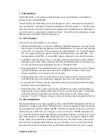
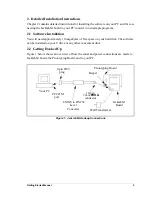
2.2.2 Jackrabbit Board
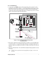
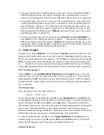
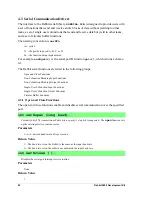
1. Connect the 10-pin
PROG
connector of the programming cable to header J3 on the
Jackrabbit board as shown in Figure 3. (If your programming cable has only one unla-
beled 10-pin connector, attach that connector to header J3 on the Jackrabbit board.)
Connect the other end of the programming cable to a COM port on your PC. Note that
COM1 is the default COM port used by Dynamic C.
Figure 3. Power and Programming Cable Connections
to Jackrabbit Board
2. Hook up the connector from the wall transformer to header J1 on the Jackrabbit board
as shown in Figure 3. The orientation of this connector is not important since the V
IN
(positive) voltage is the middle pin, and GND is available on both ends of the three-pin
header J1.
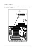
3. Plug in the wall transformer. The Jackrabbit board and the Prototyping Board are ready
to be used.
A RESET button i
s
provided on the Prototyping Board (see Figure 2) to allow a har-
ware reset.
PROTOTYPING BOARD
JACKRABBIT BOARD
JP1
U4
VIN
GND
GND
RESET
JACKRABBIT Z-World, Inc.
GND
PA0
PA2
PA4
PA6
GND
PB0
PB2
PB4
PB6
WDO
GND
PE6
PE4
PE2
PE0
HV0
HV2
K
GND
VCC
PA1
PA3
PA5
PA7
GND
PB1
PB3
PB5
PB7
PCLK
PE7
PE5
PE3
PE1
GND
HV1
HV3
+RAW
VCC
GND
RXC
TXC
PC1
PC3
PC5
PC7
AGND
DA1
PD1
PD3
PD5
PD7
GND
485+
VCC
SM1
STAT
VBAT
GND
VCC
RXB
TXB
PC0
PC2
PC4
PC6
AD0
DA0
PD0
PD2
PD4
PD6
GND
485
VCC
SM0
IOBEN
GND
/RST
J5
U6
U5
U3
J4
U1
J1
J2
J3
Y3
Rabbit 2000
SRAM
RS-232
RS-485
Colored side
lines up with
pin 1
To
PC
COM
port
PROG
DIAG
Programming
connector
Diagnostic
connector
!
Summary of Contents for 2000
Page 1: ...Rabbit 2000 Microprocessor Development Kit Getting Started 010118 D...
Page 4: ...Rabbit 2000 Development Kit...
Page 9: ...4 Rabbit 2000 Development Kit...
Page 21: ...16 Rabbit 2000 Development Kit...
Page 35: ...30 Rabbit 2000 Development Kit...
Page 36: ...Getting Started Manual Schematics...
Page 38: ...B NONE B NONE...
Page 39: ...B NONE B NONE...
Page 41: ...B NONE B NONE...
Page 43: ......


