background image

RAB Lighting is committed to creating high-quality, affordable, well-designed and energy-efficient LED lighting and controls that make it easy for electricians to install


and end users to save energy. We’d love to hear your comments. Please call the Marketing Department at 888-RAB-1000 or email: [email protected]

INSTRUCTIONS


HALV Indoor Architectural-Grade LED Wall Sconce

CLEANING AND MAINTENANCE

TROUBLESHOOTING

1.  Use warm water, mild soap and a soft sponge or cloth. Any 

acrylic cleaner may also be used. Do not use alcohol, glass 
cleaners, acetone, lacquer thinner, solvents or abrasive 
compounds. Do not use squeegees, scrapers or synthetic rags 
that may scratch the panels.

a.  Lumicor® lenses – Novus® cleaner and polish is an 

approved product for a clean shine that also protects from 
static build up. See the “General Polishing & Basic Scratch 
Repair” document at www.lumicor.com/ScratchRepair for 
more information.

2. 

DO NOT OPEN THE FIXTURE TO CLEAN THE LEDs. DO NOT 
TOUCH THE LEDs

.

1.  Check that the line voltage at the fixture is correct. Refer to 

wiring directions.

2.  Be sure the fixture is grounded properly.

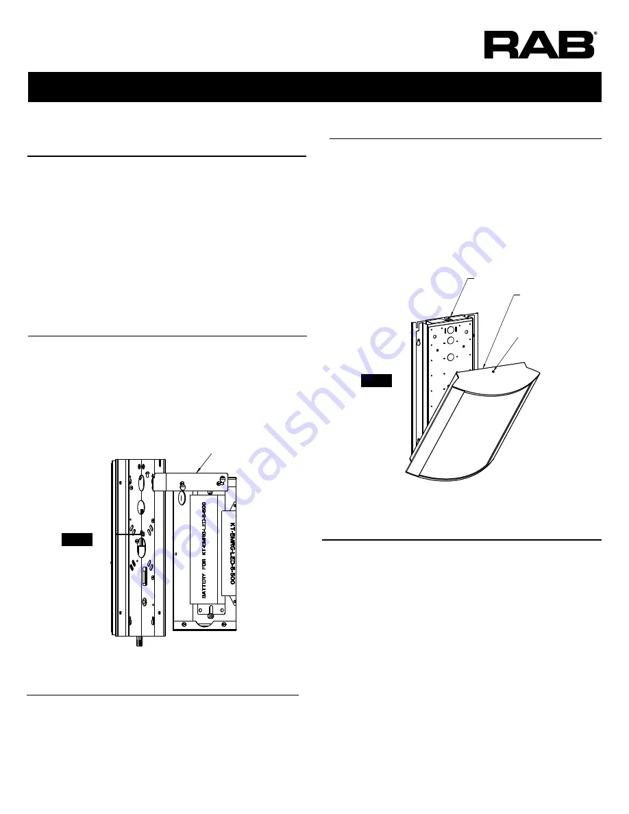
1.  Align 

Lens Frame

 over the 

Driver/LED assembly

 with the 

phillips head 

mounting screw

 at the top. See 

Figure 5

.

2.  Inset the lens frame from the bottom with the bottom flush 

against the wall. See 

Figure 5

.

3.  Tilt the top of the lens frame to the wall.
4.  Make sure the frame is flush against the wall and tighten 

mounting screw at the top using a 5/64” hex key.

LENS FRAME INSTALLATION

Driver / LED Assembly

DO NOT TOUCH LEDs

Mounting Screw

Lens Frame

FIG.5

Note:  

These instructions do not cover all details or variations in equipment nor do they provide for every possible situation during installation, operation or maintenance.

1.  Hang 

Driver/LED/Wall plate

 assembly on 

Hanger Bracket

 as 

shown in 

Figure 4

.

2.  Make wire connections.
3.  Remove 

Hanger Bracket

 and place in bottom of box for future 

use.

4.  Install Driver/LED/Wall plate and tighten 4 phillips head screws.

1.  Hang 

Driver/LED/Wall plate

 assembly on 

Hanger

 as shown in 

Figure 4 

Energize fixture. Mate battery connection.

2. 

Mate connectors, except for battery connection. Make wiring 
connections.

3. 

Energize fixture. Mate battery connection.

4.  Remove 

Hanging Bracket

 and place in bottom of box for future 

use.

5.  Install Driver/LED/Wall plate and tighten 4 phillips head screws.

DRIVER/LED/WALL PLATE/ASSEMBLY 


(with E2, E2/MVS, E2/BL, or LC/E2 Options)

DRIVER/LED/WALL PLATE/ASSEMBLY 


(with LC option)

FIG.4

Hanger

Summary of Contents for HALV

Page 1: ...s the following protocols Triac and ELV at 120V ONLY For 0 10V dimming connect purple wire to the V DIM lead and the grey wire to the V DIM lead This fixture is damp listed and suitable for indoor applications on walls Driver is 120V 277V and 50Hz or 60 Hz HALV Mounting the fixture on a standard 4 x 4 J BOX This fixture is damp listed and suitable for indoor applications on walls 1 Loosen the 4 dr...

Page 2: ... to box Wall box is installed after sheetrock 1 Remove Driver LED Wall plate assembly by loosening 4 phillips head screws as shown in Figure 1 No need to completely remove screws keyhole slots provided Retain Hanger Unplug connectors if E2 E2 MVS E2 E2 BL or LC E2 and put Driver LED Wall plate aside 2 Discard Nailer Bars 3 Move Stop Brackets from end to side and add Sheetrock Clamps as shown in Fi...

Page 3: ...e over the Driver LED assembly with the phillips head mounting screw at the top See Figure 5 2 Inset the lens frame from the bottom with the bottom flush against the wall See Figure 5 3 Tilt the top of the lens frame to the wall 4 Make sure the frame is flush against the wall and tighten mounting screw at the top using a 5 64 hex key LENS FRAME INSTALLATION Driver LED Assembly DO NOT TOUCH LEDs Mo...

Page 4: ...t at 888 RAB 1000 or email marketing rablighting com Easy Answers rablighting com Visit our website for product info Tech Help Line Call our experts 888 722 1000 e mail Answered promptly sales rablighting com Free Lighting Layouts Answered online or by request 2019 RAB LIGHTING Inc Northvale New Jersey 07647 USA DIMENSIONAL DRAWINGS LENS FRAME ASSEMBLY MODELS WITH BACK BOX LENS FRAME ASSEMBLY STAN...

Page 5: ......

Page 6: ...rred to as R for right position and L for left position when looking at sensor in orientation shown in Fig 2 in which all switches are R See Fig 1 and 2 for each setting s corresponding switches Setting options for each category are noted in parenthesis below Factory Settings designated in bold for each category Detection Area Time Delay how long lamp remains on at 100 after last recognized motion...

Page 7: ... Green LED on antenna will flash slowly for 5 seconds and fixture will blink twice if done correctly Surrounding fc will be measured and recorded for 1 second Green LED on antenna and fixture will light for 10 sec onds to indicate successful fc recording Most recent fc measurement overwrites any prior DIP settings pg 1 and ambient lux overwrite eachother depending on latest action Scene Mode 100 d...

Page 8: ...or 30 for dimmed light output after time delay passes Note These instructions do not cover all details or variations in equipment nor do they provide for every possible situation during installation operation or maintenance Easy Installation Product Help Tech Help Line Call our experts 888 RAB 1000 2016 RAB LIGHTING Inc Northvale New Jersey 07647 USA rabweb com Visit our website for product info e...

Reviews: