background image


APEX1930 USER

 MANUAL V1.0.00                                                    Tech Support: 1-888-317-8766 

12


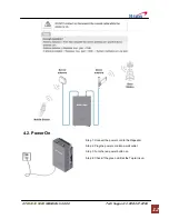
  4.2. Power On 


Step 1: Connect the power cord to the Repeater 
 
Step 2: Plug the power cord into a wall outlet. 
 
Step 3: Turn the red power button on 
 
Step 4: Check if the green LED at the Top turns on. 


Summary of Contents for APEX 1930

Page 1: ...APEX 1930 PCS Band Repeater User s Manual Please read this manual before operating this product After you finish reading this manual store it in a safe place for future reference...

Page 2: ...ABLE INSTALLATION 11 4 1 CABLE CONNECTION 11 4 2 POWER ON 12 4 3 GROUNDING 13 5 GUI OPERATION 13 5 1 GUI OPERATION FLOW CHART 14 5 2 INTERNET NETWORK SETUP 14 5 2 1 Windows 7 14 5 3 GUI LOGIN 16 5 4 G...

Page 3: ...ICATION ALARM 37 7 SPECIFICATIONS 39 7 1 RF CHARACTERISTICS 39 7 2 ENVIRONMENTAL SPECIFICATION 39 7 3 ELECTRONIC SPECIFICATION 40 7 4 MECHANICAL SPECIFICATION 40 8 APPENDIX 41 8 1 US PCS CHANNEL 41 8...

Page 4: ...tron Inc Notice This document describes the specifications installation and operation of the APEX 1930 repeater Hardware and software mentioned in this document are subject to continuous development...

Page 5: ...in very close proximity facing each other can lead to severe damage to the repeater RF EXPOSURE INFORMATION A minimum separation distance of 7 9 inches 20cm must be maintained between the user and th...

Page 6: ...tion Reason 1 3 3 WEB GUI Version History List Revision History Approval Ver Issue Ver Date Item Description Reason 1 4 Glossary The following is a list of abbreviations and terms used in this manual...

Page 7: ...D Automatic Shutdown ASD does not 1 prevent oscillation 2 protect from excessive input ASD helps protect the amplifier from over load ASD helps protect the network by preventing excessive signal outpu...

Page 8: ...such as base station fringe areas business and industrial building etc APEX1930 receives signals from a base station amplifies and retransmits the signals to the mobile stations It also receives ampl...

Page 9: ...igh performance User friendly design Local monitoring and control through the Web GUI interface Remote monitoring and control through the Web GUI interface Reports the status of connection as a functi...

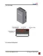
Page 10: ...APEX1930 USER MANUAL V1 0 00 Tech Support 1 888 317 8766 7 2 4 1 Overview 2 4 2 Internal Configuration...

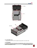
Page 11: ...upport 1 888 317 8766 8 2 4 3 RFU RF Unit The RFU RF Unit is a bi directional amplifier that sharply filters out unwanted noise 2 4 4 Duplexer A duplexer is a device that combines two or more signals...

Page 12: ...The AC DC adaptor supplies a steady DC power to the APEX1930 equipment by drawing power from the general in wall AC outlets 2 4 6 MCU Main Control Unit The MCU Main Control Unit is the control unit o...

Page 13: ...ting Grounding RF Cable Connection Power On 3 1 Mounting Step 1 Drill holes directly through the template Attach the mounting bracket to the wall using provided bolts or extra screws Step 2 Lean the A...

Page 14: ...pport 1 888 317 8766 11 Step 4 Example 4 Cable Installation 4 1 Cable Connection Step 1 Connect a cable from the donor antenna to the Donor Antenna Port Step 2 Connect a cable from a repeater s servic...

Page 15: ...00 Tech Support 1 888 317 8766 12 4 2 Power On Step 1 Connect the power cord to the Repeater Step 2 Plug the power cord into a wall outlet Step 3 Turn the red power button on Step 4 Check if the gree...

Page 16: ...uilding ground Step 2 Connect the ground cable to the rod 5 GUI Operation APEX1930 operates on a customer provided PC based platform with the following system requirements Windows XP or Windows Vista...

Page 17: ...lable Maximum Gain You can see system operating and alarm information on Status page 3 AGC control AGC automatically assigns gain 4 Manual Control Gain value setting by User Setting in order to acquir...

Page 18: ...ng Center Step 4 Click View status of Local Area Connection Step 5 Click Properties and a caution pop up window will appear Click OK Step 6 Select Internet Protocol Version 4 TCP IPv4 and click Proper...

Page 19: ...irm a User ID and type the password into the password box Type operator for the password and then click OK Step 3 The pop up message for the login success will appear Click OK Step 4 When the login pr...

Page 20: ...9 006967 Longitude W 94 532306 Refresh Time Set each refresh time for connecting to Local port and Remote port ETHERNET SETTING Ethernet IP Mode IP Address Enables you to set a connection mode for the...

Reviews: