background image

Chrysler Pacifica Minivan 

R.A.SH Tronics 


Department of R&D


11


PUSHBUTTON START MODULE 

The SS-1L-CPCF start stop system is linked to the LCD touch system and it is part of the CANbus gear selector, it is 
constantly  updated  with  the  vehicle  status  through  the  CANbus  network 
through powered gear selector module. This module should be mounted in an 
easy to reach under the steering area. 
The systems supplied with 600mm (24”) harness, it is designed to maximize the 
box mounting in-between the foot brake position switch and the engine start 
stop switch under the steering. So, it is not recommended to extend the wire 
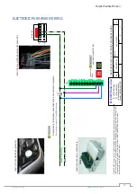
harness of the OEM modules and the start stop system. Only one OEM cable should be cut and wired to the system 
harness, all the rest are tapped into the OEM, all wires MUST be soldered, do not use any other way to tap into. 

Using the start stop function 

Depending on your input device whether it is a GID-1L or LCD touch, the start stop funtion behave exactly the same, 

the description below describe using the LCD input device for starting and stopping. The system supports two way 

starting options, the first is to shortly press to activate the ignition and then press and hold to start; the second is 

to press and hold until engine started. 

1.


When the vehicle is stationary and the ignition is Off: 

a.


Shortly press the animation key Figure A to turn on the ignition.  

b.


Shortly press a second time to turn off the ignition. 

2.


When the vehicle is stationary and the ignition is On: 

a.


Press  and  hold  the  key  until  the  engine  started,  the  symbol  changes  Figure  B 

indicating engine running.  

3.


When the vehicle is stationary and the ignition is Off: 

a.


Press and hold the animation key Figure A until the engine started and indicated by Figure B. 

Press and hold anytime to start the engine, there is no need to press the foot brake to start the engine. 

The system supports two way starting, using the short way, press and hold the key animation until the engine 

started and running. 

Start/Stop Modification Procedure 

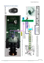
There  are  only  two  wires  to  solder  on  the  factory  board  as  can  be  seen  in  the  pictures  below. 

We  accept  no 

resonsibility for any damadge you cause to the OEM board.

 Disconnect the module from power and then comence 

the modification, double check everything before you drill/ solder or remove plastic parts. The manufacturer used 

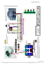
two similar wire colors in the foot brake connector (Dark Green with Brown strip), one of them when measured 

using a digital volt meeter, must show voltage level below 0.5V, this is the wire that should be cut as can be see in 

the wiring, the second wire should show voltage level abouve 2.0V, this do not cut. 

The two pins of the switch inside 

the start stop module are posite 12V, if shorted to ground, you will damage the module, it is highly recommended 

to double check yourself before connecting the battey after all wired and plugged in place.


Example of soldering two wires on the internal switch 

Identifying the start stop micro-switch 


Summary of Contents for CHRYSLER PACIFICA

Page 1: ...r mechanical including photocopying recording or by any information storage and retrieval system or translation in whole or part is NOT PERMITTED without written authorization from R A SH Tronics Ltd CHRYSLER PACIFICA MINIVAN SECONDAY CONTROLS INSTALLATION GUIDE LAST UPDATED April 13 2021 REV 03 ...

Page 2: ...ONENTS CONTINUED 7 CAN BUS GATEWAY MODULE 8 SHIFT BY WIRE CANbus MODULE 9 SHIFT BY WIRE CANbus WIRING 10 PUSHBUTTON START MODULE 11 Using the start stop function 11 Start Stop Modification Procedure 11 ENGINE START STOP WIRING 12 MULTI FUNCTION MODULE 13 HEADLIGHTS WIRING 14 ELECTRONIC PARK BRAKE WIRING 15 HVAC WINDOWS MIRRORS MODULE 16 HAZARD WARNING LIGHTS 17 EGRESS MODULE WIRING 18 VOICE SCAN W...

Page 3: ...wiring diagrams is vehicle specific It should be applied only to the vehicle indicated Depending on the system you are installing you may not install every harness v Read modules placement first it is very important to understand were to connect and fit the CAN Bus based components to avoid future problems v This manual becomes an integral part of the vehicle the system installed in You should the...

Page 4: ...ssion a Powered gear selector Vehicles using power cable for direct control of the gear box b CANbus gear selector Vehicles using electronic control unit for shifting 3 Ignition and Engine start 4 Parking Brake 5 Turn signals with automatic cancelling function a Canceling systems using CANbus steering position b Timers controlled by the stop light switch c Magnets under the steering for position d...

Page 5: ... SH Tronics Ltd All ri ghts res erved Reproducti on by a ny means electroni c graphi cs GUI or mecha ni cal i ncl uding photocopyi ng recording or by a ny i nforma ti on s torage a nd retrieval s ys tem or trans la tion i n whol e or pa rt i s NOT PERMITTED wi thout wri tten a uthori zati on from R A SH Troni cs Ltd IL Supported functi ons Power Wi ndows Power Door l ocks Power Sli ding doors HVAC...

Page 6: ...ing Manual for further details VEHICLE INTERFACE MODULE VAC 212 Through this dual CANbus gateway module which is connected to the steering module communication network it is possible to control almost all of the steering functions like turn signals horn wipers lights cruise and many more It is also used to collect real time information and update the LCD display CANbus GEAR SELECTOR ENGINE START S...

Page 7: ...size easy to use can be mounted within easy reach of the driver It is designed to access the in motion functions like turn signals and horn INPUT DEVICES DIY 1L twelve momentary switches input device This module is used to access up to twelve functions in the vehicle using low effort switches Can be mounted under the steering and hardwired to different switches located within easy reach of the dri...

Page 8: ... using the mounting tabs on the module The CAN Gateway Module is responsible to wake up and put to sleep of all system components so be sure to connect the wires utilizing proper soldering practices according to SAE J1292 FUNCTIONS CONTROLED THROUGH CANbus NO PHYSICAL WIRING REQUIRED Windows Up Down 1 Driver 2 Passenger HVAC Heating ventilation and air conditioning Fan speed 7 steps o Fast o Slow ...

Page 9: ...fact that the system collects the vehicle speed combined with the foot brake information makes it easy to operate the system by pressing the gear buttons shortly not using the Long Short press mode once Reverse button is pressed while the vehicle is driving in a high speed even if the foot brake is slightly pressed no shifting is possible Another important feature is that this vehicle has no gear ...

Page 10: ... or by a ny i nforma ti on s tora ge a nd retri e va l s ys tem or tra ns l a ti on i n whol e or pa rt i s NOT PERMITTED wi thout wri tten a uthori za ti on from R A SH Troni cs Ltd IL YEL CAN_L Size Scale CAGE Code DWG NO Rev Sheet of Tuesday April 13 2021 2 3 A4 A 059 957 746 R A SH Tronics Ltd T 972 48517656 F 972 48523339 CHRYSLER PACIFICA CAN bus Gear Selector RSM 50X CPCF rashtronix gmail c...

Page 11: ...press a second time to turn off the ignition 2 When the vehicle is stationary and the ignition is On a Press and hold the key until the engine started the symbol changes Figure B indicating engine running 3 When the vehicle is stationary and the ignition is Off a Press and hold the animation key Figure A until the engine started and indicated by Figure B Press and hold anytime to start the engine ...

Page 12: ...H TOP OF BRAKE PEDAL ASSEMBLY RLY6 87a RLY6 30 RLY6 87 IDENTIFYING THE ENGIEN START STOP SWITCH ON RIGHT SIDE OF STEERING Res i s tor Suppl i ed wi th the ki t 2019 R A SH Troni cs Ltd Al l ri ghts res erved Reproducti on by a ny mea ns el ectroni c gra phi cs GUI or mecha ni ca l i ncl udi ng photocopyi ng recordi ng or by a ny i nforma ti on s tora ge a nd retri eva l s ys tem or tra ns l a ti o...

Page 13: ...en a uthori za ti on from R A SH Troni cs Ltd IL TB3 30 87 87a 30 87a 87 30 87a 87 30 87a 87 Relay 1 Relay 7 Relay 5 Relay 3 BLK GND GRY Horn GRY Horn RED BAT ORG BRN BLU GRN Dont even think to shorten the CAN wires supplied with the kit use as is F1 5A FUSE RED BAT BLK GND IDENTIFYING THE STEERING CONTROL MODULE TOP OF STEERING COLUMN 4 DK BLU WHT CAN_H 2 YEL CAN_L DK GRN PPL Horn 1 BLK GND RED B...

Page 14: ... CHRYSLER PACIFICA MULTI FUNCTION HEADLIGHTS WIRING VAC 212 CPMF_2 rashtronix gmail com 2021 R A SH Troni cs Ltd Al l rights res erved Reproduction by any mea ns electroni c gra phi cs GUI or mecha ni ca l including photocopyi ng recordi ng or by a ny i nforma ti on s tora ge a nd retrieva l s ys tem or tra ns la ti on in whol e or pa rt is NOT PERMITTED wi thout written a uthori za tion from R A ...

Page 15: ...2 48523339 CHRYSLER PACIFICA ELECTRONIC PARK BRAKE WIRING VAC 212 CPMF rashtronix gmail com 30 IDENTIFYING THE VAC 212 CPMF MODULE 2021 R A SH Troni cs Ltd Al l ri ghts res erved Reproducti on by a ny mea ns el ectroni c gra phi cs GUI or mecha ni ca l i ncl udi ng photocopyi ng recordi ng or by a ny i nforma ti on s tora ge a nd retri e va l s ys tem or tra ns l a ti on i n whol e or pa rt i s NO...

Page 16: ...CC CPSEC rashtronix gmail com SW VAC 12LCC CPSEC hex 2020 R A SH Troni cs Ltd Al l ri ghts re s erved Reproducti on by a ny mea ns el ectroni c gra phi cs GUI or mecha ni ca l i ncl udi ng photocopyi ng recordi ng or by a ny i nforma ti on s tora ge a nd retri eva l s ys tem or tra ns l a ti on i n whol e or pa rt i s NOT PERMITTED wi thout wri tten a uthori za ti on from R A SH Troni cs Ltd IL CO...

Page 17: ...ING VAC 212 CPMF_2 rashtronix gmail com TB3 30 87 87a 30 87a 87 30 87a 87 30 87a 87 Relay 1 Relay 7 Relay 5 Relay 3 IDENTIFYING THE VAC 212 CPMF MODULE Rel ay 7 30 Rel ay 7 87 IDENTIFYING THE HAZARD SWITCH LOCATION AC MODULE ON CENTER CONSOL 5 8 4 1 WHT BLU HZ BLK GND 2021 R A SH Troni cs Ltd Al l ri ghts res erved Reproducti on by a ny mea ns el ectroni c gra phi cs GUI or mecha ni ca l i ncl udi...

Page 18: ... lengthen the cable It is recommended to shorten the battery cables as much as possible To vehicle electrical system Power Distribution System To Vehicle Starting Charging System POWER GROUND CHASISS BLU WHT 18AWG BLU YEL 18AWG POWER GROUND CHASISS F2 ADD 5A FUSE VEHICLE PRIMARY BATTERY AUX BATTERY To LCD module 1 5 J2 IDENTIFYING THE AUX BATTERY MODULE EGRESS MODULE Mus t be mounte d i ns i de th...

Page 19: ...ATT or IGN GND IDENTIFYING THE OEM RADIO BACK SIDE IDENTIFYING THE DRIVER SIDE SPEAKER Driver door speaker wire Driver door speaker wire SPK 30 SPK 30 SPK 87A SPK 87A Mute relay Size Scale CAGE Code DWG NO Rev Sheet of Sunday October 18 2020 1 1 A4 A 059 957 746 R A SH Tronics Ltd T 972 48517656 F 972 48523339 Intelligent Voice Scan Wiring Consept IVS 1X rashtronix gmail com Ba ttery when s ta rt ...

Page 20: ... singel or dual zone This touch button can do three functions Shortly press to decreas the fan speed one step Press and hold to constantly decrease the fan speed until button released If the button continue to be depressed for more than 2 seconds the HVAC will be turned off Shortly press this touch button to turn on the HVAC and increase the fan speed one step Press and hold to constantly increase...

Page 21: ...onics Department of R D 21 Shortly press this touch button decrease Cold the tempereture one step Press and hold to constantly decrease the temperature until the button released or the maximm temperature reached USING THE CRUISE CONTROL ...

Page 22: ...Chrysler Pacifica Minivan R A SH Tronics Department of R D 22 Stand Alone Functions ...

Page 23: ...GES CURRENT RATING BLACK BLK 0 3mm AWG22 5A BROWN BRN 0 5mm AWG20 7A 13A RED RED 0 85 mm AWG18 9A 17A ORANGE ORG 1 28 mm AWG16 12A 22A YELLOW YEL 2 mm AWG14 16A 30A VIOLET VLT 3 mm AWG12 21A 40A GRAY GRY WHITE WHT TAN TAN PINK PNK PURPLE PPL BLUE BLU LIGHT BLUE LT BLU DARK BLUE DK BLU GREEN GRN LIGHT GREEN LT GRN DARG GREEN DK GRN Soldering Method The soldering method shown at right is offered for...

Reviews: