6. COMPLETING
THE
INSTALLATION
Glass
shade
Glass
frame
Bulb
Screws
Screws
Wire plug
Light plate
Flange
Screws and
lock washers
Blade
support
plates
Blades
Blade
slot
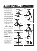
1.
Make sure the wiring is safely inside
the outlet box as instructed in
Step 5
-Electrical Connections.
To install the
canopy, remove one of the two screws
from the bottom of the mounting bracket
and loosen the other screw one turn. Slide
the canopy up to mounting bracket and
place the key hole on the canopy over the
screw on the mounting bracket, turn canopy
until it locks in place at the narrow section
of the key holes. Secure by tightening the
two set screws.
NOTE:
Adjust the canopy
screws as necessary until the canopy and
canopy cover are snug. (Fig. 9)
2.
Blade Assembly & Installation (Fig. 10)
Using the supplied blade screws and lock
washers and blade support plates, attach the
blades to the motor assembly by sliding
blades through blade slots. In some cases
the lock washer is permanently fixed to
the screw head. Ensure all screws are used
for each blade.
DO NOT bend the blades
when installing the blades.
3.
Attaching the Switch Housing (Fig. 11)
While holding the switch housing under your
fan, snap together the cannon plugs. Then
install the switch housing onto the flange
by using the three (3) screws and rubber
washers provided that are pre-installed on
the flange. Be sure to tighten all screws.
4.
Attaching the Light Plate (Fig. 12)
Connect the two wiring plugs from the
switch housing to the corresponding plug
in the light plate. Attach the light plate to
the switch housing by using the three (3)
screws provided that are preinstalled on
the switch housing.
5.
Attaching the Light Bulb , Glass
Shade and Glass Frame (Fig. 13)
Install one 9W LED bulb (included). Raise
glass shade up against light plate and
secure it to the fan by turning clockwise
until snug.
DO NOT OVERTIGHTEN.
Attach the glass frame to the light plate by
using the four screws provided that are
pre-installed on the light plate.
A certain amount of wobble may be
considered normal, especially if the fan is
on a downrod long than 12".
Fig. 10
Fig. 9
Fig. 12
Fig. 11
Fig. 13
Canopy
Screws
Outlet box
Hanger bracket
Canopy cover
Cannon plug
Switch housing
Rubber
washers
Switch
housing
Light plate


