background image

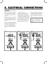
5. ELECTRICAL CONNECTIONS

Fig. 8

Fig. 8a

Fig. 8b

Outlet box

Fan switch

on wall

Ceiling

REMEMBER 

-Turn off the power!

WH

BLUE

BLK

WH

BLK

House 

supply 

wire

GROUND

GRN

3.

 Optional Wall Controls: 

Wiring connections for optional wall 

control are shown in Fig. 8a and 8b. 

Figure 8a shows how to wire a fan wall 

control switch. This controls the fan only. 

To separately control an optional light kit 

using the light kit pull chain, you would 

have to connect the blue wire from the fan 

to the house supply wire, before it goes to 

the wall control. This is not an easy 

connection, and we suggest you call a 

qualified electrician to do it for you.

4.

 Inside the ceiling junction box be sure 

to spread the wires apart so that the black 

and blue connections are on one side of 

the outlet box and the white/white and 

green/copper connections are on the other 

side.

Use the wire nuts supplied with your fan 

when making connections. Secure the 

connectors with electrical tape and make 

sure there are no loose connections or 

wire strands.

1.

 Spread the wires apart so that the black 

and blue wires from the fan are on one 

side of the mounting bracket and the white 

wire and green ground wire are on the 

other side.

2.

 (Fig. 8) Connect the BLACK building 

supply wire to the BLACK and BLUE fan 

wires. Connect the WHITE building 

neutral wire to the WHITE fan neutral 

wire. Connect the COPPER building 

ground wire to the GREEN fan ground 

wire.

Use 

ONLY

 wall controls approved by 

Quorum. Use of unapproved wall 

controls will cause unacceptable 

humming noise, and avoids the fan 

warranty.

Outlet box

Ceiling

WH

BLUE

BLUE

BLUE

BLK

WH

BLK

BLK

BLK

GROUND

GRN

Fan/light 

switch

on wall

House 

supply 

wire

Outlet box

Ceiling

WH

BLUE

BLUE

BLUE

BLK

WH

BLK

BLK

BLK

BLK/WH

GROUND

GRN

Fan 

Fan 

Fan 

Summary of Contents for Niles

Page 1: ...se read and save these instructions P O Box 961008 Fort Worth TX 76161 817 626 5483 FAX 817 626 5540 I0340 02 22 These instructions are to be used in the installation of the following QUORUM INTERNATI...

Page 2: ...s to ensure your warranty is registered If you have any questions regarding the warranty or the procedures for obtaining service please call us at 817 626 5483 Monday thru Friday 8 00 a m 5 00 p m CST...

Page 3: ...ers Electrical Tape Step Ladder IF YOU FIND THAT PARTSARE MISSING CONTACTYOUR DEALER FOR REPLACEMENT OR CALL QUORUM DIRECTLYAND WE WILL MAIL REPLACEMENTS TO YOU IMMEDIATELY 2 UNPACKING YOUR FAN 10 Do...

Page 4: ...building structure using a wood screw not included Fig 7 Fig 6 Fig 7 Fig 5 Downrod assembly Canopy Canopy cover Yoke cover Downrod Hanger bracket Safety cable 1 Disconnect the power by removing fuses...

Page 5: ...the white white and green copper connections are on the other side Use the wire nuts supplied with your fan when making connections Secure the connectors with electrical tape and make sure there are...

Page 6: ...for each blade DO NOT bend the blades when installing the blades 3 Attaching the Switch Housing Fig 11 While holding the switch housing under your fan snap together the cannon plugs Then install the...

Page 7: ...ower speed than summer 2 Periodically check tightness of all screws securing the blades to the blade arm attachment points A clicking or a rattling noise is a sure indication of loosening screws Since...

Page 8: ...Use of a standard light rheostat or an unapproved fan wall control to control the fan speed will always cause an annoying hum Many fan motors do not work quietly with solid state variable speed contro...

Reviews: