background image

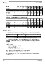
Models


QOCS
25

QOCS
53

QOCS
106

QOCS
180

QOCS
360

QOCS
636

QOCS
1325

QOCS
2650

QOCS
5300

Cold climate

l/s

16

33

67

113

227

400

833

1666

3332

Cold climate

cfm

34

71

141

240

480

848

1766

3532

7065

Mild climate

l/s

12

25

50

85

170

300

625

1250

2500

Mild climate

cfm

25

53

106

180

360

636

1325

2650

5300

Hot climate

l/s

6

12

24

41

83

146

304

608

1216

Hot climate

cfm

13

26

52

88

175

309

645

1289

2578

Installation with compressors, air receivers and filters:

Models


QOCS
25

QOCS
53

QOCS
106

QOCS
180

QOCS
360

QOCS
636

QOCS
1325

QOCS
2650

QOCS
5300

Cold climate

l/s

20

42

83

142

283

500

1042

2083

4167

Cold climate

cfm

42

88

176

300

601

1060

2208

4417

8833

Mild climate

l/s

15

31

63

106

213

375

781

1563

3125

Mild climate

cfm

32

66

133

225

451

795

1656

3313

6625

Hot climate

l/s

9

17

34

57

114

201

420

839

1678

Hot climate

cfm

18

36

71

121

242

427

890

1779

3558

Correction factors

For operation in conditions other than reference conditions, multiply the compressor capacity
(FAD) in the tables above with the corresponding correction factors.

Running hours per
day

12

14

16

18

20

22

24

Correction factor

1.00

0.86

0.75

0.67

0.6

0.55

0.5

The condensate treatment device is designed to operate 12-hour duty cycles or less. If the
compressor is running more than 12 hours per day, the appropriate correction factor must be
considered.

Example

Working condition:

• Ambient temperature = 25 °C (77 °F)
• Relative humidity = 60%
• Compressor running hours = 24
• Correction factor = 0.5 (see table above)

QOCS 360 at reference conditions (with dryer): 170 l/s (360 cfm)

QOCS 360 at working condition: 170 x 0.5 = 85 l/s (180 cfm)

Max Compressor FAD of 85 l/s (180 cfm) can be connected to a QOCS 360 unit at above
working conditions.

Instruction book

24

2920 7197 51

Summary of Contents for QOCS 25

Page 1: ...Quincy Condensate management QOCS 25 QOCS 53 QOCS 106 QOCS 180 QOCS 360 QOCS 636 QOCS 1325 QOCS 2650 QOCS 5300 Instruction book...

Page 2: ......

Page 3: ...of the contents or any part thereof is prohibited This applies in particular to trademarks model denominations part numbers and drawings This instruction book is valid for CE as well as non CE labell...

Page 4: ...R REPAIR 5 1 6 DISMANTLING AND DISPOSAL 5 2 General description 7 2 1 INTRODUCTION 7 2 2 OPERATION 7 3 Installation 12 3 1 DIMENSION DRAWINGS 12 3 2 INSTALLATION PROCEDURE 13 4 Operating instructions...

Page 5: ...ion 1 Install the equipment where the ambient air is cool and as clean as possible Consult section Reference conditions and limitations 2 During installation or any other intervention on the equipment...

Page 6: ...Persons switching on remotely controlled machines shall take adequate precautions to ensure that there is no one checking or working on the machine To this end a suitable notice shall be affixed to t...

Page 7: ...with due care to ensure that they function properly They may not be put out of action 9 Before clearing the device for use after maintenance or repair check that operating pressures temperatures and t...

Page 8: ...in symbol At the end of life time of the electric and electronic equipment EEE it must be taken to separate collection For more information check with your local waste authority customer center or dis...

Page 9: ...vibration because of the use of filters and can be used with all types of drains The condensate meets the requirements of the environmental codes The number in the model designation is the air capacit...

Page 10: ...let 1 into the mufflers 3 and is depressurized The condensate flows to the first stage and seeps through an oleophilic filter 4 which absorbs most of the oil The water from the first tower still conta...

Page 11: ...o the first tower and seeps through an oleophilic filter 3 which absorbs most of the oil The water from the first stage still containing a small quantity of oil gradually flows to a second stage where...

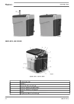
Page 12: ...2650 QOCS 5300 1 Condensate inlet 2 Mufflers 3 Oleophilic filters first stage 4 Service indicator oleophilic filter 5 Service indicator unit clogged 6 Drain 7 Organoclay filters second stage Instruct...

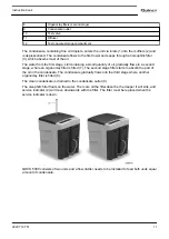
Page 13: ...where an organoclay filter is fitted 7 The second stage filter starts to absorb the part of the oil in the condensate The condensate gradually flows into the third stage where another organoclay filt...

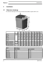
Page 14: ...9 C mm 216 216 428 507 576 721 970 1000 1000 C inch 9 9 17 20 23 28 38 39 39 Shipping weight kg Organ oclay 2 4 3 0 7 5 11 17 32 56 115 240 Shipping weight lb 5 3 6 6 17 24 38 71 123 254 529 Operating...

Page 15: ...e drains that are feeding it whenever possible The drain tube that is mounted to the outlet of the oil water separator must incline downwards over its entire length The reason for this is to avoid acc...

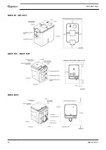
Page 16: ...QOCS 25 QOCS 53 QOCS 106 QOCS 1325 QOCS 2650 Instruction book 14 2920 7197 51...

Page 17: ...atic drain of the compressor condensate trap to the condensate inlet of the unit The connection can be made using one or both condensate inlets The piping diameter must be at least 6 mm for QOCS 25 53...

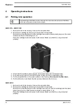
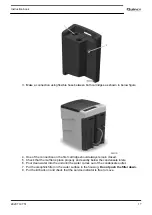
Page 18: ...3 Check that the muffler is place properly and exactly below the condensate inlets 4 Pour clean water into the unit until the water comes out of the condensate outlet 5 Put the oleophilic filter on th...

Page 19: ...Check that the muffler is place properly and exactly below the condensate inlets 6 Pour clean water into the unit until the water comes out of the condensate outlet 7 Put the oleophilic filter on the...

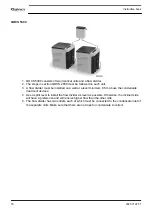
Page 20: ...e the condensate treatment devices 4 Use a spirit level to install the flow divider as level as possible Otherwise the inclined side will have a preference and will receive higher flow than the other...

Page 21: ...since every compressor installation can burden its separator in a variety of ways it is difficult to make a general prediction regarding the lifetime of the separator Therefore it is advised to check...

Page 22: ...ch deteriorate the ability to break oil water emulsions 4 Remove the diffuser and pull out the mufflers See section Introduction 5 Fit the new mufflers and diffuser 6 Go to section Filter replacement...

Page 23: ...QOCS 360 8102 0470 30 Manifold for QOCS 636 up to QOCS 5300 8102 0470 31 Wall mounting bracket for QOCS 25 QOCS 53 An optional wall mounting bracket is available to mount the unit on the wall Wall mou...

Page 24: ...ment device Check the compressor FAD see section Technical data Cloudy condensate at the outlet Improper sizing It is possible that the compressor produces stable and strong emulsions due to various e...

Page 25: ...Mild climate ambient temperature of 25 C 77 F and relative humidity of 60 Hot climate ambient temperature of 35 C 95 F and relative humidity of 70 Limitations for operation Minimum ambient temperature...

Page 26: ...Hot climate l s 9 17 34 57 114 201 420 839 1678 Hot climate cfm 18 36 71 121 242 427 890 1779 3558 Correction factors For operation in conditions other than reference conditions multiply the compress...

Page 27: ...Separation performance For an outlet oil carry over of 5 mg l instead of 10 mg l multiply the compressor capacity FAD in the tables above by 1 2 Instruction book 2920 7197 51 25...

Page 28: ......

Page 29: ......

Page 30: ...No 2920 7197 51 2021 05 Printed in Belgium Performance You Demand Reliability You Trust www quincycompressor com...

Reviews: