Section VI - Servicing
Quincy Compressor
®
- QSB/T
™
29
Belt Drive Inspection Procedure
1)
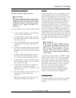
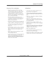
Inspect sheave grooves for nicks.
2)
Thoroughly inspect the tapered bore of the sheave
and the tapered surface of the bushing. Any paint,
dirt, metal chips, fluid or grease must be removed.
3)
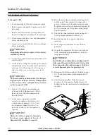
Position bushing and sheave assemblies and rough
align with a metal straight edge. Mount sheaves as
close to the compressor and/or motor housing as
practical to avoid excessive bearing and shaft
loads. Tighten dry capscrews evenly and
alternately. Do not use lubricants in this
installation. Excessive capscrew tightening can
cause sheave and/or bushing breakage. Rotate
pulleys to check for sheave runout (wobble) or a
bent shaft. Hand tighten setscrew over keyway, if
required.
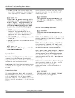
NOTICE!
After tightening, there should be a 1/8” to 1/4”
gap between the mating part hub and the bushing
flange.
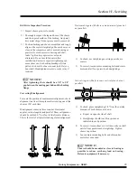
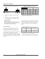
Correcting Misalignment
To locate the position of maximum misalignment, check
alignment in at least three places after rotating one of the
sheaves 120° each time.
Misalignment comes in three varieties: Horizontal
angular, vertical angular and parallel. Sheave alignment
should be within 0.07” per foot of shaft center distance.
This is the total of all parallel and angular misalignment.
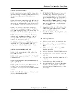
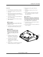
Horizontal Angular (Shafts in same horizontal plane but
not parallel)
1)
To check, use straightedge or string near sheave
centers.
2)
To correct, loosen motor mounting bolts and rotate
motor until all four points touch straightedge.
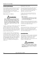
Vertical Angular (Shafts in same vertical plane but not
parallel)
1)
To check, place straightedge 1/4” from the outside
diameter of both sheaves as shown:
a. Repeat on opposite side of shaft.
b. Straightedge should touch four points as
indicated in each position.
2)
To correct, loosen sheave so it slides easily on shaft
until all four points touch straightedge. Tighten
sheave in position.
3)
Loosen motor mounting bolts and shim under
motor feet as needed.
NOTICE!
Sheave should be mounted as close to bearing as
possible to reduce overhung load on bearing.
Relocate equipment, if necessary.
Summary of Contents for QSB Series
Page 2: ......
Page 9: ...Section I General Quincy Compressor QSB T 5 MODEL IDENTIFICATION...
Page 21: ...Quincy Compressor QSB T 17 THIS PAGE INTENTIONALLY LEFT BLANK...
Page 27: ...Quincy Compressor QSB T 23 THIS PAGE INTENTIONALLY LEFT BLANK...
Page 71: ...Quincy Compressor QSB T 67 THIS PAGE INTENTIONALLY LEFT BLANK...
Page 72: ...Appendix A Dimensional Drawings 68 Quincy Compressor QSB T QSB 15 50 HP air cooled...
Page 73: ...Appendix A Dimensional Drawings Quincy Compressor QSB T 69 QSB 15 50 HP water cooled...

