background image

1-888-QUIETCOOL 

16

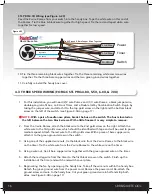
STL PRO-3.3X Wiring (see Figure 4.2C)

Feed the 2 wire Romex from your switch into the handy box. Tape the white wire on this end of 

the Romex. Tie the blue & black wire together for high speed. Tie the red and taped white wire 

together for low speed.

10. Tie the three remaining black wires together. Tie the three remaining white common wires  

  together. Tie the three bare copper wires and the two green ground wires together.  

11. Carefully reinstall the handy box cover.

Power

Timer

Tie All Ground & Bare Copper Wires Together

Whole House Fan

14-2 Wire

14-2 Wire

Switch

14-2 Wire

Low Speed

High Speed

White Common Wires Together

Black Wires Together

White - Marked w/ Tape

Black

Figure 4.2C

4.3  THREE SPEED WIRING (FOR QC STL PRO-4.8X, 5.5X, 6.0X, & 7.0X)

1.  For this installation, you will need (2) 2 wire Romex and (1) 3 wire Romex, a black jumper wire,  

  double-gang retrofit box, an 8 Hour Timer, and a Double 3-Way Combination Switch. Begin by  

  taking the jumper wire, and attach it to the top gold screw on the right and the bottom black   

  screw on the left of the switch. (see Figure 4.3A on page 17)   


NOTE:

 With a pair of needle nose pliers, break the bus on the switch. The bus is located on 

    the left between the two black screws. With a little finesse it is very simple to remove. 

2.  From the 3 wire Romex, attach the black wire to the 2nd gold screw on the right. Attach the 

  white wire to the 3rd gold screw, which should be identified with tape and will be used to power 

  medium speed. Attach the red wire to the 4th gold screw. With a piece of bare copper wire, 

  attach it to the green ground screw on the switch.  

3.  Using one of the supplied wire nuts, tie the black wire from the 2 wire Romex to the black wire  

  on the timer. Tie the white wire from the 2 wire Romex to the white wire on the timer. 

4.  Using a wire nut, tie all bare copper wires together with the green ground wire on the timer. 

5.  Attach the red leg wire from the timer to the first black screw on the switch. Finish up the 

  installation of the timer and switch and switch cover plate. 

6..  Begin wiring the fan by opening up the handy box. Take off the wire nuts within the handy box. 

  Detach the green ground wire from the power cord. Remove the power cord. Re-attach the 

  ground screw and wire to the handy box. Cut your green ground wire in half and strip both 

  sides. (see Figure 4.3B on page 17) 

!

!

Summary of Contents for STEALTH PRO-1.5X

Page 1: ...DO NOT THROW AWAY SERIAL NUMBER FOR FAN IS LOCATED ON THE BACK COVER OF THE OWNER S GUIDE LEAVE WITH HOMEOWNER OWNER S GUIDE STEALTH PRO X WHOLE HOUSE FAN...

Page 2: ...TED IMPORTANT READ BEFORE INSTALL 8 3 INSTALLATION 10 3 1 Installing QuietCool 10 3 2 Installing Vertical Adapter 12 4 WIRING 13 4 1 Single Speed Wiring QC STL PRO 1 5X 13 4 2 Two Speed Wiring QC STL...

Page 3: ...equivalent to a loud vacuum cleaner running The QuietCool system uses a cutting edge patented design to get our sound levels down to a respectable level Our fans suspend in the attic and use an acoust...

Page 4: ...arly evening is spent in the kitchen or family room area Assuming this to be true this is where you would want to start the cooling process Begin opening a few windows in the area you are going to be...

Page 5: ...healthier If you have any trouble installing or operating your new QuietCool whole house fan or for more tips on running the QuietCool please visit our website www QuietCoolSystems com or call us at...

Page 6: ...obstruction F HIGH PERFORMANCE ACOUSTICAL DUCTING Noise dampening technology with insulated ducting that is used to separate the Steel Housing from the living space G AIRTIGHT DAMPER BOX Damper Box w...

Page 7: ...ould with 1 750 attic venting But don t worry the system will still operate if there is not enough venting Insufficient venting is a very simple problem to fix Roofing contractors can add extra ventin...

Page 8: ...Care should be taken to avoid backdrafting combustion appliances that are installed in the conditioned space Whole house fans are capable of pulling large quantities of air from the home particularly...

Page 9: ...ST your QuietCool unit before installation using the included power cord If the fan does not work call us immediately SPECIAL INSTRUCTIONS TO CONTRACTORS 1 DO NOT take the Owner s Guide with you after...

Page 10: ...pencil 4 Using a drywall saw or similar device cut out the hole in the ceiling TIP If your attic is very tight you may want to wire your QuietCool motor housing before bringing it into the attic Plea...

Page 11: ...fasten the damper box to both the drywall and the joist in the attic NOTE Remember that you must fasten the damper box to the ceiling joists AND drywall The purpose of this is to make sure the damper...

Page 12: ...side of the vertical adapter Place the vertical adapter with the T side up onto the damper box with the side that has only two flanges flush on the damper box 2 If you have studs spaced at 16 on cent...

Page 13: ...ard wire the fan or it is required by your local building codes please follow the wiring instructions below WELCOME INSTALLATION WIRING OPERATION WARRANTY 4 1 SINGLE SPEED WIRING FOR QC STL PRO 1 5X 1...

Page 14: ...ft of the switch Finish up the installation of the timer and switch and switch cover plate 7 Begin wiring the your fan by opening up the handy box Take off the wire nuts within the handy box Detach th...

Page 15: ...Feed the 2 wire Romex from your timer into the handy box Feed the 2 wire Romex from your power source into the handy box STL PRO 2 5X Wiring see Figure 4 2B Feed the 2 wire Romex from your switch into...

Page 16: ...Figure 4 3A on page 17 NOTE With a pair of needle nose pliers break the bus on the switch The bus is located on the left between the two black screws With a little finesse it is very simple to remove...

Page 17: ...Tie the three bare copper wires and the two green ground wires together 10 Carefully reinstall the handy box cover Power Timer Tie All Ground Bare Copper Wires Together Whole House Fan 14 2 Wire 14 2...

Page 18: ...ly When the HIGH LOW OFF Switch is in the middle position the fan will be off regardless of the setting on the Timer With the switch in the top position the fan will be on HIGH With the switch in the...

Page 19: ...the operation of our equipment or any malfunction thereof 2 Cost of service calls to diagnose the cause of problems or the labor charge to un install any components 3 Product failure or damage due to...

Page 20: ...FAN SERIAL NUMBER INFORMATION RETAIN FOR YOUR RECORDS SERIAL NUMBER IS REQUIRED FOR WARRANTY PURPOSES 1 888 QUIETCOOL WWW QUIETCOOLSYSTEMS COM Rev 3 11 21...

Reviews: