background image

31

GB

SBC NRG HIGH POWER - REV001A

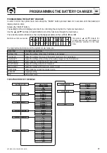
PROGRAMMING THE BATTERY CHARGER

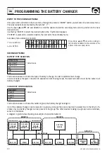
CAN PRIORITY SETTINGS

PRIORITY CAN

Priority 1 *

* Default value

Priority 2
Priority 3
Exit

This function is used to determine the priority level of the battery charger within the network group.
The use of this function is needed where there are battery chargers in parallel inside a group.
If there are two battery chargers in parallel, set on one unit the “

Priority 1

” and set on the other the “

Priority 2

”; if 

there are three battery chargers in parallel, set respectively the “

Priority 1

”, “

Priority 2

” and “

Priority 3

”.

A battery charger set with “Priority 1” must always be present inside the group.
In case only one battery charger is present in the group, then set it as “

Priority 1

”.

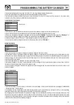
MONITOR MODE

MONITOR MODE

Disable *

* Default value

Enable
Exit

This function allows to enable or disable the battery charger’s “Monitor” mode.
The “Monitor” mode, if activated, allows the battery charger to transmit and receive data on the CAN network, even 
without the AC mains, obtaining power supply from the battery bank connected to the MASTER output. This allows the 
battery charger to communicate with the terminals present on the CAN network and keep the control panel active 
even without the AC mains.
The current absorption, in “Monitor” mode, is lower than 70 mA.
The battery charger in “monitor” mode switches off if the voltage of the master battery bank is lower than 7 Vdc for 
models 12 Vds and lower than 14 Vdc for models 24 Vdc.
In case of battery chargers connected in parallel (current sharing mode), the selected option must be the same in all 
battery chargers.

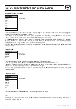
FLOAT THRESHOLD

FLOAT THRESHO

5%
10%
15%
20% *

* Default value

25%
30%
Exit

This function allows to set the value, in the form of a percentage, of the FLOAT threshold (see paragraph “OPERATION 
- Charge features - FLOAT phase).
For example, for the model SBC 1200 NRG FR (maximum rated current100A) by setting the 20%, a corresponding 
absolute value of the FLOAT threshold of 20A (20% of 100A) will be obtained. 
By changing the FLOAT threshold, the batteries’ charge can be optimized according to their capacity. Moreover, this 
function can be used to allow the correct shift into the FLOAT phase in case of constant absorption (caused by a load 
connected to the battery bank). In case of battery chargers connected in parallel (current sharing mode), the selected 
option must be the same in all battery chargers

The devices belonging to one group  “

A

”, “

B

” o “

C

” can only dialog between themselves. 

Group “

U

” (Universal) is an exception as this can dialog with any other device.

The distinction between different groups is very important in order to connect all the devices to the same CAN 
network even if they belong to different electrical systems.

Summary of Contents for SBC 1100 NRG FR

Page 1: ...ty Nautical Equipment Manuale di installazione ed uso CARICABATTERIE SBC NRG Manual of installation and use SBC BATTERY CHARGER NRG IT GB SBC NRG HIGH POWER SBC 1200 NRG FR SBC 1450 NRG HR SBC 1950 NRG HR SBC 2450 NRG HR ...

Page 2: ......

Page 3: ...lemi con reset manuale problemi con reset automatico Pag 18 SEGNALAZIONI messaggi di avvertimento messaggi di stato Pag 19 MANUTENZIONE DATI TECNICI INDICE INDEX IT GB Pag 20 21 CHARACTERISTICS AND INSTALLATION Pag 22 INSTALLATION OPERATION equipment supply Pag 23 OPERATION batteries Pag 24 OPERATION control signals Pag 25 26 OPERATION Can Bus network connection Pag 27 OPERATION charging character...

Page 4: ...pulsanti Modalità di potenza ridotta automatica e manuale Interfaccia utente multilingua Interfaccia CAN BUS per il trasferimento dati INSTALLAZIONE L installazione del caricabatterie deve essere effettuata da personale qualificato PRIMA DI UTILIZZARE IL CARICABATTERIE LEGGERE ATTENTAMENTE IL PRESENTE MANUALE D USO IN CASO DI DUBBI CONTATTARE IL RIVENDITORE O IL SERVIZIO CLIENTI QUICK In caso di d...

Page 5: ...erminali di uscita specificati nella seguente tabella MODELLO SBC 1200 NRG FR SBC 1450 NRG HR SBC 1950 NRG HR SBC 2450 NRG HR Tensione batterie 12 V 24 V Capacità batterie 450 1000 Ah 270 600 Ah 360 800 Ah 450 1000 Ah Sezione minima cavo di uscita 50 mm2 25 mm2 35 mm2 50 mm2 Numero di celle della batteria 6 12 MODELLO SBC 1200 NRG FR con 2 unità in parallelo SBC 1450 NRG HR con 2 unità in parallel...

Page 6: ...oni alla rete AC devono essere realizzate in accordo alle norme locali relative agli impianti elettrici ATTENZIONE prima di collegare o scollegare il cavo AC del caricabatterie dalla rete AC accertarsi che quest ul tima sia disconnessa tramite interruttore bipolare Prima di collegare o scollegare i cavi DC dai terminali di uscita del caricabatterie accertarsi che l apparecchio sia disconnesso tram...

Page 7: ... polarità potrebbe danneggiare seriamente il caricabatterie anche se protetto tramite fusibili FIG 2A FIG 2B L2 L1 L3 J L BATTERIA FIG 2 PART A PART B BATTERIE Per accedere ai terminali di uscita è necessario rimuovere il coperchio svitando le due viti che lo serrano in alto fig 2 part A Prima di effettuare i collegamenti dei cavi provenienti dalla batteria allentare o smontare i relativi serracav...

Page 8: ...egato al punto di giunzione JM il punto di giunzione JM deve essere collegato al polo positivo della batteria o del gruppo batterie fig 2A Il terminale positivo SLAVE 1 del caricabatterie deve essere collegato al punto di giunzione JS1 il punto di giunzione JS1 deve essere collegato al polo positivo della batteria o del gruppo batterie fig 2A Il terminale positivo SLAVE 2 del caricabatterie deve e...

Page 9: ...isposti Di seguito si riporta un esempio di collegamento della rete per singolo caricabatterie CAN IN CAN OUT 1 2 3 4 ON 1 2 3 4 5 6 7 8 ON 1 2 3 4 5 6 7 8 ON 1 2 3 4 5 6 7 8 ON 1 2 3 4 5 6 1 2 3 4 ON 1 2 3 4 5 6 CAN IN CAN OUT 2 1 8 1 2 8 1 1 SBC NRG TERMINAZIONE DISATTIVATA TERMINAZIONE ATTIVATA DIP SWITCH RDS 1521 RDS 1541 DIP SWITCH CONNETTORE TERMINAZIONE Dispositivi opzionali COLLEGAMENTO PI...

Page 10: ...OWER DIP SWITCH RDS 1521 RDS 1541 DIP SWITCH CAN IN CAN OUT 1 2 3 4 ON 1 2 3 4 5 6 7 8 ON 1 2 3 4 5 6 7 8 ON 1 2 3 4 5 6 7 8 ON 1 2 3 4 5 6 1 2 3 4 ON 1 2 3 4 5 6 CAN IN CAN OUT 8 1 2 8 1 2 1 2 1 2 1 2 1 2 1 1 CAN IN CAN OUT 2 8 1 CAN IN CAN OUT 2 8 1 CAN IN CAN OUT CAN IN CAN OUT 8 1 1 2 1 2 DIP SWITCH RDS 1521 RDS 1541 DIP SWITCH OPZIONE COLLEGAMENTO TERMINALI REMOTI OPZIONE COLLEGAMENTO TERMINA...

Page 11: ... V V absorption I IMAX ith absorption float BULK ABSORPTION FLOAT NUOVO CICLO TEMPO TEMPO V float A seconda del tipo di carica programmata Nel caso siano collegati i caricabatterie in parallelo modalità di ripartizione di corrente il valore IMAX deve essere moltiplicato per il numero di caricabatterie 2 o 3 Il valore di default della soglia di passaggio tra ABSORBTION e FLOAT è pari al 20 del valo...

Page 12: ... della tensione sui terminali di usci ta Il simbolo che compare in questa zona indica il numero e la posi zione dei messaggi di stato presenti nella coda circolare Indicazione relativa alla misura della corrente totale erogata dalle tre uscite del singolo caricabatterie Indicazione dello stato del sistema stato di carica stato generico messaggi di avvertimento o problemi con reset automatico Esemp...

Page 13: ...DO MONITOR Permette l abilitazione o la disabilitazione della modalità monitor SOGLIA FLOAT Permette l impostazione della soglia di FLOAT CORRENTE MAX Permette l impostazione della massima corrente di uscita MODO SILENZ Permette l abilitazione o la disabilitazione della modalità silenziosa LANGUAGE Impostazione della lingua dei messaggi di sistema USCITA Uscita dal menù SCHEMA DELLA STRUTTURA DEI ...

Page 14: ...essere la stessa in tutti i caricabatterie CONFIGURAZIONE GRUPPO CAN CAN GROUP Gruppo A Impostazione di fabbrica Gruppo B Gruppo C Uscita Questa funzione permette di stabilire a quale gruppo di rete appartiene il caricabatterie SBC 2450 NRG HR PRIORITÀ 2 SBC 1200 NRG FR GRUPPO A GRUPPO B GRUPPO U RETE CAN RDS 1521 RDS 1560 RDS 1521 RDS 1560 INTERFACCIA GSM TERMINALE LCD All interno di un gruppo po...

Page 15: ...onitor è inferiore a 70 mA Il caricabatteria in modalità di Monitor si spegne se la tensione del gruppo batterie master è inferiore a 7 Vdc per i modelli a 12 Vdc e inferiore a 14 Vdc per i modelli a 24 Vdc Nel caso di caricabatterie collegati in parallelo modalità di ripartizione di corrente l opzione selezionata deve essere la stessa in tutti i caricabatterie SOGLIA DI FLOAT SOGLIA DI FLOAT 5 10...

Page 16: ...e collegati in parallelo modalità di ripartizione di corrente l opzione selezionata deve essere la stessa in tutti i caricabatterie USCITA Per uscire dal menù principale o da un sottomenù portarsi con i pulsanti p e q UP e DOWN sulla opzione USCITA e confermare con il tasto ENTER MODALITÀ SILENZIOSA MODO SILENZ Disabilitato Impostazione di fabbrica Abilitato Uscita Questa funzione permette di limi...

Page 17: ...a da parte di un centro assistenza Quick PROBLEMI CON RESET MANUALE Per eliminare i problemi con reset manuale bisogna rimuovere la causa che li ha generati disconnettere il caricabatte rie dalla rete AC per almeno 10 secondi e riconnetterlo Con questa tipologia di problemi il caricabatterie interrompe l erogazione di potenza COD MESSAGGIO DESCRIZIONE 31 Sovratemper La temperatura ambiente è maggi...

Page 18: ... un valore maggiore uguale a 11 Vdc mod SBC 1200 NRG FR o 22 Vdc mod SBC 1450 NRG HR SBC 1950 NRG HR SBC 2450 NRG HR 62 Batt M alta La tensione della batteria o del gruppo batterie misurata sul terminale di uscita MASTER è maggiore di 14 8 Vdc mod SBC 1200 NRG FR o 29 6 Vdc mod SBC 1450 NRG HR SBC 1950 NRG HR SBC 2450 NRG HR La segnalazione scompare non appena la tensione si riporta ad un valore m...

Page 19: ...0 A Tensione di carica in absorption 14 1 Vdc EL aperta 14 4 Vdc EL sigillata Gel AGM 28 2 Vdc EL aperta 28 8 Vdc EL sigillata Gel AGM Tensione di carica in float 13 4 Vdc EL aperta 13 8 Vdc EL sigillata Gel 13 6 Vdc AGM 26 8 Vdc EL aperta 27 6 Vdc EL sigillata Gel 27 2 Vdc AGM Assorbimento DC dalle batterie 2 3 5 mA 5 mA Ondulazione residua 3 100 mV RMS Caratteristiche di carica Automatica a tre ...

Page 20: ...backlit LCD display with 3 buttons Automatic and manual power derating mode Multi language user interface CAN BUS interface for data transfer INSTALLATION The installation of the battery charger must be carried out by qualified personnel BEFORE USING THE BATTERY CHARGER CAREFULLY READ THIS USER S MANUAL IF IN DOUBT CONTACT YOUR NEAREST DEALER OR QUICK CUSTOMER SERVICE In case of discordance or err...

Page 21: ...pecified in the following table MODEL SBC 1200 NRG FR SBC 1450 NRG HR SBC 1950 NRG HR SBC 2450 NRG HR Battery voltage 12 V 24 V Battery capacity 450 1000 Ah 270 600 Ah 360 800 Ah 450 1000 Ah Minimum output cable size 50 mm2 25 mm2 35 mm2 50 mm2 Number of battery cells 6 12 MODEL SBC 700 NRG FR 2 units in parallel SBC 1100 NRG FR 2 units in parallel SBC 1950 NRG HR 2 units in parallel SBC 2450 NRG ...

Page 22: ...mains must be carried out according to local electrical codes WARNING before connecting or disconnecting the battery charger s AC cord from the AC mains please make sure it is disconnected by bipolar switch Before connecting or disconnecting the DC wires from the battery charger s output terminals please ensure that the device is disconnected by means of bipolar switch from the AC mains and by mea...

Page 23: ...ing charge batteries can generate explosive gases there fore avoid sparks or naked flames Provide adequate ventilation to the battery area whilst charging WARNING before connecting the batteries check the polarity of the ca bles from the battery Reversing the polarity could seriously damage the battery charger even if protected by fuses OPERATION FIG 2A FIG 2B L2 L1 L3 J L BATTERY FIG 2 PART A PAR...

Page 24: ...ted to junction JCN junction JCN is to be connected to the negative terminal of the battery or group of batteries fig 2A The lengths of cables that run from the terminals of the battery chargers to the junctions must be the same and never exceed 2 m fig 2B If the installation has only one or two groups of batteries always connect the output marked MASTER This is the main output of the battery char...

Page 25: ... terminals An example of a network connection is given below CAN IN CAN OUT 1 2 3 4 ON 1 2 3 4 5 6 7 8 ON 1 2 3 4 5 6 7 8 ON 1 2 3 4 5 6 7 8 ON 1 2 3 4 5 6 1 2 3 4 ON 1 2 3 4 5 6 CAN IN CAN OUT 2 1 8 1 2 8 1 1 SBC NRG TERMINATION DEACTIVATED TERMINATION ACTIVATED DIP SWITCH RDS 1521 RDS 1541 DIP SWITCH TERMINATION CONNECTOR Optional devices CAN OUT 4 4 5 5 FIG 4 PIN 4 CAN OUT CONNECTION STATE HIGH...

Page 26: ...S 1541 DIP SWITCH CAN IN CAN OUT 1 2 3 4 ON 1 2 3 4 5 6 7 8 ON 1 2 3 4 5 6 7 8 ON 1 2 3 4 5 6 7 8 ON 1 2 3 4 5 6 1 2 3 4 ON 1 2 3 4 5 6 CAN IN CAN OUT 8 1 2 8 1 2 1 2 1 2 1 2 1 2 1 1 CAN IN CAN OUT 2 8 1 CAN IN CAN OUT 2 8 1 CAN IN CAN OUT CAN IN CAN OUT 8 1 1 2 1 2 DIP SWITCH RDS 1521 RDS 1541 DIP SWITCH REMOTE TERMINALS CONNECTION OPTION REMOTE TERMINALS CONNECTION OPTION SBC NRG HI POWER SBC NR...

Page 27: ...ion I IMAX ith absorption float BULK ABSORPTION FLOAT NEW CYCLE TIME TIME V float Depending on the type of charge programmed In case the battery chargers are connected in parallel current sharing mode the IMAX value must be multiplied by the number of battery chargers 2 or 3 The default value of the transition threshold between ABSORPTION and FLOAT is equal to 20 of the maximum nomi nal value of t...

Page 28: ...rameters and confirm selections A quick pressure and release of the keys leads to the lighting up of the backlighting for 30 seconds Information concerning the voltage measure on the output termi nals The symbol which appears in this area shows the number and the position of the status messages present in the circular queue Information concerning the total current supplied by the three outputs Sta...

Page 29: ...XIT Open Liquid Sealed Liquid GEL AGM Group A Group B Group C Exit 5 10 15 20 25 30 Exit Exit Priority 1 Priority 2 Priority 3 Exit Disable Enable Exit 100 90 80 70 60 50 Disable Enable Exit English Italiano SILENT MODE Francais Espanol Deutsch Exit The programmable functions in the systems main menu are u B A T T E R Y T Y P E t c a n G R ou p q PROGRAMMING THE BATTERY CHARGER In order to enter t...

Page 30: ... only one battery charger can be present in the group The other devices making up a group can be terminals sensors or interfaces A diagram is given below showing an example of a possible network SECONDARY MENU SBC 2450 NRG HR PRIORITY 1 SBC 2450 NRG HR PRIORITY 3 æ B A T T E R Y T Y P e P O P E N L i q u i d q CAN NETWORK ENTRY TO THE SECONDARY MENU Once you select a function in the main menu thro...

Page 31: ...sorption in Monitor mode is lower than 70 mA The battery charger in monitor mode switches off if the voltage of the master battery bank is lower than 7 Vdc for models 12 Vds and lower than 14 Vdc for models 24 Vdc In case of battery chargers connected in parallel current sharing mode the selected option must be the same in all battery chargers FLOAT THRESHOLD FLOAT THRESHO 5 10 15 20 Default value...

Page 32: ...er In case of battery chargers connected in parallel current sharing mode the selected option must be the same in all battery chargers EXIT To exit from main menu and submenu use the p and q UP and DOWN buttons to scroll to the entry EXIT and con firm with by pressing ENTER SILENT MODE SILENT MODE Disable Default value Enable Exit This function allows to reduce the acoustic noise generated by the ...

Page 33: ...move the cause that generated it disconnect the battery charger from the AC mains for 10 seconds and than reconnected With this type of problems the battery charger stops supplying power COD MESSAGE DESCRIPTION 31 Overtemperat The ambient temperature is higher than 70 C The battery charger suspends the output power supply which will start again once the ambient temperature is back to a lower value...

Page 34: ... SBC 1450 NRG HR SBC 1950 NRG HR SBC 2450 NRG HR 62 Batt M hi The battery s or battery bank s voltage measured on the MASTER output terminal is higher than 14 8 Vdc mod SBC 1200 NRG FR or 29 6 Vdc mod SBC 1450 NRG HR SBC 1950 NRG HR SBC 2450 NRG HR As soon as the voltage goes back to a lower equal value to 14 8 Vdc the notification disappears mod SBC 1200 NRG FR or 29 6 Vdc mod SBC 1450 NRG HR SBC...

Page 35: ... 100 A 60 A 80 A 100 A Charge absorption voltage 14 1 Vdc EL open 14 4 Vdc EL sealed Gel AGM 28 2 Vdc EL open 28 8 Vdc EL sealed Gel AGM Charge float voltage 13 4 Vdc EL open 13 8 Vdc EL sealed Gel 13 6 Vdc AGM 26 8 Vdc EL open 27 6 Vdc EL sealed Gel 27 2 Vdc AGM DC absorption from the batteries 2 3 5 mA 5 mA Residual ripple 3 100 mV RMS Charging characteristics Automatic in three stages IUoU Numb...

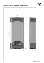
Page 36: ...36 SBC NRG HIGH POWER REV001A SBC HIGH POWER NRG DIMENSIONI DIMENSIONS mm 220 542 557 243 116 ...

Page 37: ...NOTES ...

Page 38: ...SBC NRG HIGH POWER REV001A NOTES ...

Page 39: ...39 SBC NRG HIGH POWER REV001A ...

Page 40: ...ane 120 A 48124 Piangipane RAVENNA ITALY Tel 39 0544 415061 Fax 39 0544 415047 www quickitaly com E mail quick quickitaly com SBC NRG HIGH POWER R001A Codice e numero seriale del prodotto Product code and serial number GB IT ...

Reviews: