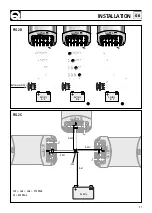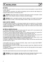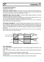
26
OPERATING
GB
ON/STAND-BY BUTTON:
Use this button to put the battery charger in stand-by mode. To activate this mode simply press the button
quickly (press and release in less than one second). To take the battery charger out of stand-by mode,
press the button quickly again or disconnect the battery charger from the AC power supply and then
connect it up again.
CONTROL PANEL
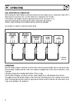
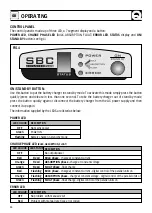
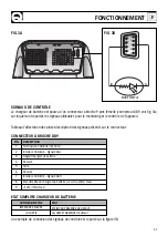
The control panel is made-up of three LED, a 7 segment display and a button:
POWER LED
,
CHARGE PHASE LED
(BULK, ABSORPTION, FLOAT)
ERROR LED
,
STATUS
display and
ON/
STAND-BY
button (see fig.4).
The information supplied by the LEDS are listed as below:
POWER LED
CHARGE PHASE LED
(BULK, ABSORPTION, FLOAT)
ERROR LED
DESCRIPTION
No output power
BULK
phase
- charge at constant current
ABSORPTION phase -
charge at constant voltage
FLOAT
phase
- float charge
BULK
phase
- charge at constant current - digital control of the parallel units on
ABSORPTION phase
- charge at constant voltage - digital control of the parallel units on
FLOAT
phase
- float charge - digital control of the parallel units on
LED COLOUR
OFF
Green
Flashing
DESCRIPTION
No mains power
Power ON
Battery charger in stand-by mode
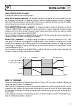
FIG.4
LED COLOUR
OFF
Red
Orange
Green
Red
Orange
Green
LED STATUS
-
Fixed
Fixed
Fixed
Flashing
Flashing
Flashing
LED COLOUR
OFF
Red
DESCRIPTION
No problem with manual reset
Problem with manual reset (see error codes)


