


LTE Module Series
EC21 Hardware Design
EC21_Hardware_Design Confidential / Released 34 / 94
Module
VBAT_RF
VBAT_BB
VBAT
C1
100uF
C6
100nF
C7
33pF
C8
10pF
+
+
C2
100nF
C5
100uF
C3
33pF
C4
10pF
D1
5.1V
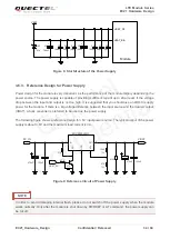
Figure 8: Star Structure of the Power Supply
3.6.3. Reference Design for Power Supply
Power design for the module is very important, as the performance of the module largely depends on the
power source. The power supply is capable of providing sufficient current up to 2A at least. If the voltage
drop between the input and output is not too high, it is suggested that you should use an LDO to supply
power for the module. If there is a big voltage difference between the input source and the desired output
(VBAT), a buck converter is preferred to be used as the power supply.
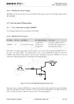
The following figure shows a reference design for +5V input power source. The typical output of the power
supply is about 3.8V and the maximum load current is 3A.
DC_IN
MIC29302WU
IN
OUT
E
N
G
N
D
A
D
J
2
4
1
3
5
VBAT
100nF
470uF
100nF
100K
47K
470uF
470R
51K
1%
1%
4.7K
47K
VBAT_EN
Figure 9: Reference Circuit of Power Supply
In order to avoid damaging internal flash, please do not switch off the power supply when the module
works normally. Only after the module is shut down by PWRKEY or AT command, the power supply can
be cut off.
NOTE
Quectel
Confidential


