background image


QF1200S; edition 2016-05; page 11 of 24   


3.9. Further warning and safety instructions 

These warning hints are to prevent the user from an inadmissible mode of operation. These 
warning hints are to be strictly followed to avoid any damage of the pump and/or any danger to 
personnel 

The maximum allowed discharge pressure depends on the temperature of the fluid: 

pmax at room temperature = 6 bar (>40°C = 4 bar) ) [=87 psi (>104°F = 58 psi)]

An exceeding of the maximum allowed discharge pressure must avoid in any case (do 
not remove the warning sign at the pump). As a result – if only temporarily – of an 
exceeding of the allowed discharge pressure the diaphragm can be damaged. The 
resulting leakage may lead to a loss of the pumping fluid and damages of properties 
and/or persons. Pay attention to a sufficiently dimensioned piping on the suction and 
discharge line to prevent a too high pressure in the pump. 

The pump chamber may 

not be set under pressure when it is not mounted on the drive.


The free cross section of the suction side as well as the length must be measured in 
such a way to avoid cavitation.    


The use of a safety device (e.g. pressure switch) can be necessary..


Please make sure that prior to the start of the pump the discharge line is checked. 
Make sure that there is no flow restriction in the discharge line to avoid any over 
pressure (e.g. closed valve). 


Flush the pump prior to use with appropriate fluid (e.g. buffer). 


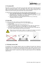
Foundation design: The foundation must be designed so that it can take the weight of 
the pump aggregate on the entire surface.  . 


Please make sure that the pump is operated with the proper mains voltage and 
frequency to avoid damages and electrical danger. 


Make sure that the slots for the cooling air are not blocked. 


Due to the versatile possibilities to use the Quattroflow pump it is highly 
recommended to check case by case if the pump will be the right tool for the specific 
application. The user/operator is responsible to perform a proper method of testing if 
the pump should be applied for his specific application. The chemical and thermal 
compatibility of the elastomeric parts of the pump with the fluid that will be pumped 
are to be checked by the operator before the first process run.


E.g. Oily, fatty fluids or 

solvents might cause a swelling and/or destruction of the elastomeric components. If 
in doubt, please contact the manufacturer! 


Operating the pump in humid or aggressive air can cause damages to the motor and 
control box. 


The control box should not be exposed to spray/splash water or to heat sources.  


Depending on the conditions of operation, the liquid conveyed might escape from the 
pump in case of a diaphragm rupture. For further safety requirements the optional 
equipment diaphragm monitoring is recommended. 


Pools of liquid which appear in the near outer area of the pump have to be inspected 
on danger potential, if necessary safety measures are to be taken. 


Chemical and biological reactions in the product chamber of the pump (mixture of 
different substances) and the freezing of the liquid have to be avoided. 


To avoid corrosion the contact of aggressive solutions (e.g. NaCl, HCl) with the outer 
stainless steel surfaces of the pump (e.g. hood, base plate) has to be prevented. 


The Quattroflow pump is a positive displacement pump and can theoretically generate 
an infinitely high pressure even at low speed (rpm). Prior to each start of the pump 
check and make sure that the discharge line is not closed or restricted. The design of 
the discharge line must not build up a pressure of > 6 bar (87 psi). 


If suction and/or discharge line are flexible tubing, then make sure that these tubing 
do have the proper pressure rating for the full range of temperatures that are applied. 


Please follow the general safety guidelines when handling chemical fluids (wear 
gloves and/or glasses) before the pump chamber will be opened. 


Never operate the pump without coupling protection and motor housing. 

Summary of Contents for 1200S

Page 1: ...a are of a ope At d the w Orig and tructi 00S Qu Piston ultiple U eft hand and odel image m ersions are p l carefu an appr rating s ttentio warning inal In Insta ions uaterna Diaph Use with separa mid...

Page 2: ...ety instructions for maintenance inspection and mounting operations 10 3 7 Unauthorized reconstruction and spare part usage 10 3 8 Inadmissible modes of operation 10 3 9 Further warning and safety ins...

Page 3: ...and mechanical influences The following storage conditions are recommended Steady ventilated dust and vibration free storage room Ambient temperature between 15 C 59 F and 25 C 77 F with a relative hu...

Page 4: ...omatography columns Feed pump to mix gradients Feed pump for centrifuges or separators Feed pump for homogenizers Feed pump for filling machines 2 2 General description of the machine The Quattroflow...

Page 5: ...aOH can be applied The chosen cleaning agent can be recirculated and also stored inside the pump chamber For flushing out of any cleaning agent do not recirculate Check with appropriate analytical met...

Page 6: ...00S CV via the control panel Display show rpm V max speed 2 200 rpm Main switch Push to start the panel lights up Push to speed up arrow bottom up or to speed down arrow top down Push Green button RUN...

Page 7: ...ersonnel should change the parameter of the control panel on the back of the panel via DIP switches Attention Pay attention to the separate operating instructions of the ENGEL Motor QF1200S HT Pumpe M...

Page 8: ...we recommend the following steps 1 CIP of the pump chamber according to 2 4 or any other suitable process 2 Empty the pump 3 Remove the pump chamber from the pump drive see 4 1 1 4 Close in and outlet...

Page 9: ...strictly the safety guidelines of this manual as well as all national and possible internal regulations e g the handling of chemicals like caustic or acid the handling of biological materials the han...

Page 10: ...tart up and check the tightness of the pump o Please respect the relevant additional security advices if the pump has been used for aggressive dangerous or toxic liquids e g suitable protective equipm...

Page 11: ...the right tool for the specific application The user operator is responsible to perform a proper method of testing if the pump should be applied for his specific application The chemical and thermal c...

Page 12: ...led personnel Check the electrical cables before connecting to mains supply During all maintenance work it has to be ensured that no explosive atmosphere can arise Appropriate protection equipment is...

Page 13: ...rate SIP etc it may be necessary to shorten the maintenance intervals for the elastomers significantly In case that the diaphragm broke it needs to be replaced Then it is also recommended to check the...

Page 14: ...lves can be conducted by the operator The following drawings describe it step by step maintenance kit PSKITQF12MU In case of bursting diaphragms by overpressure we advice also to change the bearing un...

Page 15: ...he following torque values Image 10 Bolts pump chamber 10 Nm 7 4 lb ft Image 10 Bolts diaphragm cover housing 5 Nm 3 7 lb ft Image 12 Bolt clamping ring 6 Nm 4 4 lb ft Turn the pump chamber until you...

Page 16: ...eccentric shaft or Maintenance kit PSKITWLC125 5 eccentric shaft for QF1200S and QF1200S HT or Maintenance kit PSKITWLC125 CV QF1200S CV The replacement of the bearing unit can be conducted by the op...

Page 17: ...r 10 Nm 7 4 lb ft Image 9 Bolt clamping ring 6 Nm 4 4 lb ft gap 1 5 mm 0 079 0 118 inch 11 Turn the pump chamber until you see the screw of the clamping ring and fix it with 5mm hex key with a torque...

Page 18: ...h size10 remove screws 1 Dismounting drive house Fitting 4x M6 wrench size10 screws with washer 1 Mounting of drive house 4 3 Disassembly assembly of the drive housing For further questions and orderi...

Page 19: ...X Pressure line completely or partly clogged diaphragm maybe broken change diaphragm 10 X The diameter of the pipes in suction or pressure line are too small 11 X Check the coupling halves They must...

Page 20: ...pump Pump rpm motor rpm If reducer gear drives are used Pump rpm motor rpm x reduction ratio 6 1 Performance standard version Eccentric shaft 3 0 10 20 30 40 50 60 70 80 0 2 4 6 8 10 12 14 0 100 200...

Page 21: ...selected motor frequency drive combination the motor frequency and the resulting pump speed might differ 0 10 20 30 40 50 60 70 80 0 2 4 6 8 10 12 14 16 18 20 22 0 200 400 600 800 1000 1200 1400 0 500...

Page 22: ...ter t ct model w 0 psi 2 arts above w he final asse ct model w 0 psi 2 arts above w he final asse with integr 29 psi 58 ps were ascertai embly of the with integr 29 psi 58 ps were ascertai embly of th...

Page 23: ...pends on installation position ca 8 26 depends on inst position ca 8 26 depends on inst position ca 8 26 depends on inst position Product wetted surface approx cm inch 367 57 367 57 367 57 367 57 Spee...

Page 24: ...d into separate Control Box Power Supply Unit separate Controller integrated in pump Power Supply Unit integrated in pump Manufacturer standard Lenze AC tech TDK Lambda power supply Panasonic Mean Wel...

Reviews: