background image

Quantum Scalar i500: Ethernet Expansion Blade Replacement

6-68020-01 Rev A

December 2013

Replacing an Ethernet Expansion Blade

3

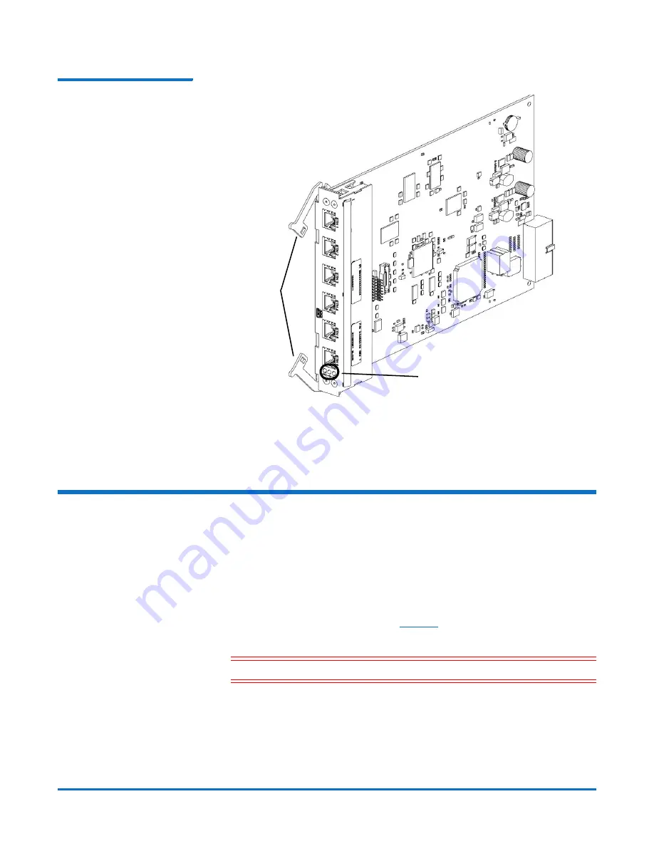
Figure 2  Ethernet Expansion 
Blade with Open Latch Hooks

4

Continue lifting on the latch hooks until the Ethernet Expansion blade is 

totally unplugged from the library’s backplane

5

Slide the Ethernet Expansion blade out of the bay.

Replacing an Ethernet Expansion Blade

These instructions explain how to install the replacement blade in the library.

1

Remove the new Ethernet Expansion blade from the protective anti-static 

bag.

2

Press up and out to open the latch hooks on each side of the blade. Hold the 

Ethernet Expansion blade upright, with the latch hooks on the left side, and 
the status LEDs at the bottom (see 

Figure 2

 on page 3).

3

Carefully align the Ethernet Expansion blade with the guide slots in the bay. 

Caution:

Forcing the blade into the bay can cause the pins to bend.

4

Evenly apply pressure to both sides of the blade and slide it into the 

expansion module until the latch hooks begin to move toward the middle of 

the blade. Push the latch hooks toward the middle of the blade and into the 

locked position. You will feel the blade pins connect with the expansion 

module’s backplane as the blade locks into place.

Latch 
hooks, 
open

LEDs

Summary of Contents for Scalar i500

Page 1: ... countries All other trademarks are the property of their respective owners Quantum specifications are subject to change Quantum Scalar i500 Ethernet Expansion Blade Replacement The Ethernet Expansion blade see Figure 1 facilitates direct Ethernet connectivity between HP LTO 5 and LTO 6 Fibre Channel tape drives and the Scalar i500 library s internal Ethernet via the library control blade Figure 1...

Page 2: ...u would if you were permanently removing or relocating the Ethernet Expansion blade For more information about permanently removing or relocating an Ethernet Expansion blade see the Quantum Scalar i500 User s Guide 1 Save the library configuration a From the Web client select Tools Save Restore Configuration b Select Save System Configuration and click Apply 2 Disconnect the Ethernet cables from t...

Page 3: ...ive anti static bag 2 Press up and out to open the latch hooks on each side of the blade Hold the Ethernet Expansion blade upright with the latch hooks on the left side and the status LEDs at the bottom see Figure 2 on page 3 3 Carefully align the Ethernet Expansion blade with the guide slots in the bay Caution Forcing the blade into the bay can cause the pins to bend 4 Evenly apply pressure to bo...

Page 4: ...d 6 Verify that the Ethernet Expansion blade is in the Ready state using one of the following methods Check the LEDs on the Ethernet Expansion blade The green LED should blink once per second the blue LED should blink once every 10 seconds and the amber LED should be off From the library Web client complete the following steps a Select Tools Diagnostics to enter library diagnostics If a message wa...

Reviews: