®
Removable Hard Disk Storage System
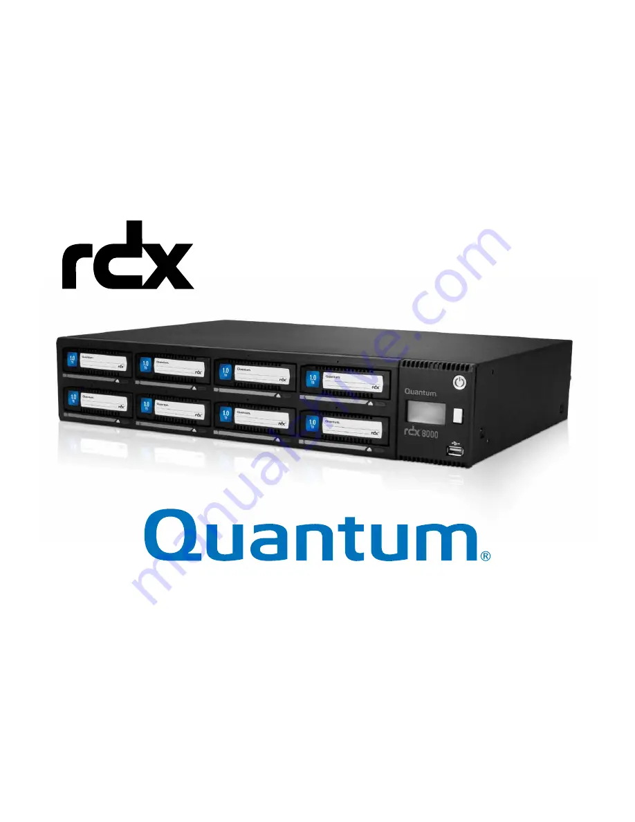
8000
User Guide
PN 6-67387-02 Rev A
Page 1: ...Removable Hard Disk Storage System 8000 User Guide PN 6 67387 02 Rev A...
Page 2: ...a Class A product based on the standard of the VCCI Council If this equipment is used in a domestic environ ment radio interference may occur in which case the user may be required to take corrective...
Page 3: ...rranty If any defect in material or manufacture appears within 1 year of the date of original purchase of this product it will be replaced or the purchase price refunded For more information go to www...
Page 4: ...2 Installation precautions 13 4 1 3 Unpacking the unit 13 4 2 Installing in a rack 15 4 3 Installing cables and connections 16 4 5 Powering up and Powering down the unit 17 5 Product configuration 18...
Page 5: ...uration 60 5 12Performing Diagnostic operations The DIAGNOSTICS tab 62 5 12 1 Device Logs 62 5 12 2 Performing diagnostics 63 5 12 3 Upgrade Firmware 68 5 12 4 Reboot 69 6 RDX cartridges 70 6 1 Write...
Page 6: ...ont panel display OCP with simple icons and provides more detailed information via RDX 8000 the Web based remote management interface 1 3 RDX cartridge features Forward and backwards compatible with a...
Page 7: ...8000 JBOD default setting The RDX 8000 unit appears to the host operating system as 8 individual RDX cartridge drives each with their own drive letter Note that depending on the host operating system...
Page 8: ...ay with RGB back light 3 OCP Navigation Button display mode selector switch used to play pause information on the operator display Also used to locally acknowledge clear error messages 4 USB 2 0 servi...
Page 9: ...Cartridge eject button LED State Status Description Off No power No cartridge inserted Steady green Ready Cartridge is inserted and the RDX is operating properly Blinking green Ejecting Unit is ejecti...
Page 10: ...ection 2 Power supply CRU For replacement see section CRU replacement Power supply 3 Product identification label 4 Hard reset port Reset system defaults For more information see section Save Restore...
Page 11: ...Number Description 1 Link Activity LED Blinking indicates a link is established Off indicates no link is established 2 Speed LED Amber on indicates a Gigabit connection 1000 Mbps Green on indicates a...
Page 12: ...EIA rack 2U space Room temperature Operating Non operating 10 40 C gradient 10 C hour 30 60 C gradient 20 C hour Power source 100 240 VAC input voltage 50 60 Hz line frequency 1 2 0 6 A Locate the RD...
Page 13: ...ss to the network connection s which will be used and an accessible AC power outlet within 6 ft of the unit NOTICE If the temperature in the room where the unit will be installed varies by 15 C 30 F f...
Page 14: ...r cord region dependent Printed Quick Start Guide RDX cartridges Confirm that you received the following in the RDX 8000 box RDX 8000 unit Rack mounting ears with included mounting hardware Torx drive...
Page 15: ...the rack for the unit to be installed 2 Use a pencil to mark the location on each vertical rail in the rack 3 Install the rack ears of the unit using T10 Torx screwdriver to tighten the Torx screws in...
Page 16: ...to avoid overheating the unit The manufacturer disclaims all liability in the event a non manufacturer approved power cord is used To connect the power cord to the unit 1 Plug the power cord into the...
Page 17: ...r button If the unit was stopped or rebooted because of an AC power interruption the unit will automatically boot backup to operation mode without the necessity of a power button push This allows the...
Page 18: ...d use this address for operations The IP address will appear on the System Information screen of the OCP 4 If after 60 seconds no DHCP server is found the unit will use the APIPA protocol to assign a...
Page 19: ...followed by eight individual screens indicating slot status Following slot 8 the rotation is repeated beginning with the System Information screen After initial power up the OCP will hold on the Syst...
Page 20: ...ately 3 seconds The OCP will change to Pause mode indicated by the OCP Navigation icon changing to the step icon To step the OCP display to the next screen when the OCP is in pause mode press and rele...
Page 21: ...otocol limits connectivity to one host connection per target Attempts by a second host to connect to a iSCSI target already connected will result in an error In JBOD mode with each slot being a separa...
Page 22: ...er click Log On or Connect 7 The RDX 8000 IQN should now change to CONNECTED 8 The RDX 8000 is now connected via iSCSI 9 If the System Mode is Tape Library In Device Manager The RDX 8000 will be ident...
Page 23: ...000 Index aspx To install the service 1 Download the RDX 8000 Utility file to a known location on your host 2 Extract the files from the zip file using Right click Extract from the operating system or...
Page 24: ...to the unit with your Web browser application by entering the RDX 8000 IP address in your browser address bar You may enter XXX XXX XXX XXX where the X s indicates the actual IP address The IP address...
Page 25: ...e RDX 8000 remote management interface via a Web browser Using the IP address visible on the unit s front panel OCP enter the IP address into your browser address bar and navigate to the RDX 8000 Logi...
Page 26: ...ication This is the location were the user enters in their specific login information Access to RDX 8000 RMI menus is granted by login levels as described in Table 6 Default User Accounts on page 26 4...
Page 27: ...features The RDX 8000 grants access or ability to perform operations based upon user rights The RDX 8000 grants the Administrator and Service levels full access to device set up diagnostics and loggin...
Page 28: ...nts is displayed below The main navigation is performed via selection via mouse click of the Main Topic Bar element 1 in the RDX 8000 page chart and then selection of the associated Sub Topics element...
Page 29: ...ll pages The System Information Block covers key global parameters related to overall system status and identification If the system has pending errors they will be indicated by the status icon and ad...
Page 30: ...rmation will be available via an information button icon located next to the status indication System Name The user configurable System Name appears at log in and with remote e mail alerts System Date...
Page 31: ...us OK indicates normal operation of the cartridge Error indicates a problem with the RDX cartridge Remaining Capacity This field shows the remaining storage capacity of the media when in tape emulatio...
Page 32: ...s label field will always display the default cartridge label when the RDX 8000 system is operated in JBOD mode When the RDX 8000 system is operated in Tape Library mode Tape format ted RDX cartridges...
Page 33: ...s used to provide access both to the RDX 8000 connection and the iSCSI connection Total Power On Time This field displays the total power on time since the last system reboot event Temperature This fi...
Page 34: ...rror The Fan Status will be set to Fan Error if the fan is not running not running at the proper speed or if an over temperature condition is sensed Power Supply Status This field displays the power s...
Page 35: ...worldwide unique address assigned to the unit The MAC address is embedded in the unit and is not changeable by the customer Link State This field displays the current status of the network connection...
Page 36: ...on the page Figure 18 RDX 8000 Monitor Device Identity Vendor ID This field shows the manufacturer of the RDX 8000 device Product ID This field shows the product name Serial Number This field shows t...
Page 37: ...red exclamation mark to indicate an abnormal condition In Disk Library mode this feature allows the user to manually move RDX cartridges from any storage slot to the identified drive The drive allows...
Page 38: ...38 RDX 8000 User Guide Figure 19 RDX 8000 Manage Library...
Page 39: ...ject and require that they are ejected through the software application In JBOD mode connecting to an iSCSI host will put the cartridges in Ejection Protection mode disabling ejection via the Web inte...
Page 40: ...used in JBOD mode or Disk Library mode NOTICE Converting the RDX cartridge into tape format mode or reformatting from tape format back to disk format mode destroys any previously written user data on...
Page 41: ...tten user data on the cartridge The RDX cartridge will contain no user data and will be blank Re formatting tape format RDX cartridges back to standard RDX disk To convert previously tape formatted RD...
Page 42: ...he choices are Tape Library Disk Library and JBOD If you choose Tape Library or Disk library mode there is an additional field which appears allowing the configuration of the drive count 1 to 3 drives...
Page 43: ...to apply the changes A confirmation dialog will appear as follows NOTICE A change in the operating mode of the RDX 8000 may cause the device to become unavail able for data access for your particular...
Page 44: ...o be associated with a given drive letter NOTICE Usage of the RDX 8000 in tape library mode requires pre formatting of the RDX cartridges into the tape format mode before they may be used with tape ba...
Page 45: ...set both a daily power on time and a daily power off time and choose to enable each one individually The power off time will shut down the unit at the configured and enabled shutdown time regardless...
Page 46: ...label up to 25 characters long This custom label will both be displayed in the RDX 8000 and shown as the volume label in the tape backup application It is strongly recommended that if the user intends...
Page 47: ...DX 8000 Configure Ethernet MTU Size The Maximum Transmission Unit MTU Size controls the maximum data packet size over the network The choices are 1500 and 9000 1500 is the default size Stack The Stack...
Page 48: ...P address and other network parameters set on this page for network communication IP Address Manually assigned IP address that the RDX 8000 will use for network communication Netmask Netmask used for...
Page 49: ...twork To save any changes on this page click the Submit button 5 11 5 iSCSI Settings iSCSI settings are accessed on the CONFIGURE iSCSI tab Figure 28 RDX 8000 Configure iSCSI Target IQN The user to ca...
Page 50: ...anagement and configuration of iSCSI devices from a central point If this option is enabled the RDX 8000 will register its resources with a central iSNS server To enable iSNS on the RDX 8000 click the...
Page 51: ...o gain access to the iSCSI bridge Target Secret This is the secret defined by the iSCSI bridge and will be sent from the ISCSI Initiator to authenti cate the iSCSI Initiator The Target secret field ha...
Page 52: ...not be deleted The following fields are required for each user account Username The login name of the user account Requirements are must be 3 to 16 characters no special characters must begin with a l...
Page 53: ...nit to remote users There are four tabs related to configuring the time on the RDX 8000 unit Time Zone The Time Zone tab allows the user to specifically adjust the time to their local time zone To use...
Page 54: ...and entering the date in the appropriate format and click Done The time may be set by clicking in the time field and entering the time Clicking the Now button will synchronize the RDX 8000 system time...
Page 55: ...ts English MM DD YYYY European DD MM YYYY International YYYY MM DD The time settings support display of either 12 hour or 24 hour time displayed in the following format 12 hours hh mm ss AM PM 24 hour...
Page 56: ...56 RDX 8000 User Guide Figure 35 RDX 8000 Configure Date Time Format...
Page 57: ...synchronize with the NTP time server every eight hours To use the NTP time synchronization select Enable and enter the name or IP address of the desired time server Click the Submit button for the set...
Page 58: ...ction and will allow the user to configure the e mail parameters Figure 37 RDX 8000 Configure Notification Notification Filter Select from four classes of notification as follows Critical Events Notif...
Page 59: ...r to handle to e mail notifications Security Select to enable either SSL LS or STARTTLS security if necessary Port Enter the send receive port number for the e mail traffic E mail Address Enter the e...
Page 60: ...ng the file Figure 38 RDX 8000 Configure Save Restore NOTICE It is highly recommended that once the initial unit configuration is completed and the unit is operating properly the user use the save con...
Page 61: ...ault passwords IP addressing and operating modes Depending on network settings resetting defaults may cause loss of communication with the unit or require you to adjust network settings to regain acce...
Page 62: ...potential use problems or command failures Warnings typically relate to either incorrect configuration of the RDX 8000 device cartridge format or attempts to perform operations which are logically ph...
Page 63: ...10 seconds then releasing The unit display will then change to the message System Test Display A description of the display diagnostic test follows The display will perform the following 1 Display Sy...
Page 64: ...an Test It tests the operation of the RDX 8000 cooling fan steps the fan speed through four RPM ranges while monitoring fan rpm Cartridge Access Test It tests the operation of each slot location by ch...
Page 65: ...ion of a successful test by selecting Test Passed button which will create a Slot UI Test passed status Display Test Figure 42 Display Test To execute the Display Test select the Start Test button The...
Page 66: ...Test Results Once the fan test has completed the RDX 8000 will report a pass fail status and the user may click the OK button to log the result Cartridge Access Test The Cartridge Access Test checks...
Page 67: ...insert a cartridge in each of the eight slots in sequence The RDX 8000 unit will then perform the slot access test and eject the cartridge and provide a pass fall status Upon completion of testing of...
Page 68: ...s have an fbi file extension and are approximately 22MB in size Click the Browse button to set a path to the RDX 8000 firmware file located on the computer system connect via RDX 8000 then select the...
Page 69: ...tely via the DIAGNOSTICS Reboot tab selecting the Reboot tab and clicking the Reboot button Rebooting the unit takes approximately 3 5 minutes and will require the user to log in to the RDX 8000 again...
Page 70: ...on page 75 Figure 50 Cartridge overview RDX cartridges contain HDDs with SATA I or SATA II interfaces capable of transferring data at either 1 5 GB s or 3 0 GB s 6 1 Write protecting cartridges The wr...
Page 71: ...ridges Front Panel Cartridge Eject button Eject via RDX 8000 Web interface Manually eject cartridge via Emergency Eject Port Figure 53 Ejecting cartridges Front Panel Cartridge Eject button When allow...
Page 72: ...e ejected by inserting a straightened paperclip or similar device into the Emergency Eject Port until resistance is felt Then provide a firm push to eject the cartridge NOTICE When using the emergency...
Page 73: ...scription Possible solution LOAD tape failed not formatted as RDX 8000 tape The device is configured in Tape mode but inserted cartridge is not configured as a Tape cartridge Cartridge is writable Mak...
Page 74: ...ture on CPU board exceeds lower alarm level Fan and or system airflow is ob structed Temperature on local sensor over high limit Temperature on CPU board exceeds higher alarm level Fan and or system a...
Page 75: ...Storage Temperature 30 60 C Non operating Temperature Gradient 20 C hour Relative Humidity Operating 20 80 non condensing Relative Humidity Non operating 20 90 non condensing Operating humidity Gradi...
Page 76: ...lass A FCC 47CFR Part 15B 2008 07 Limit Class A Test acc to CISPR 22 ICES 003 Issue 4 2004 03 Limit Class A Test acc to CISPR 22 AS NZS 3548 1995 A1 A2 1997 Limit Class A VCCI V 3 2009 04 in parts Jap...
Page 77: ...screws located on the rear of the power supply using a 3 Phillips screwdriver or your fingers 5 Pull the power supply straight out of the unit 6 To store or ship the removed power supply repackage it...
Page 78: ...of the cooling fan using a 3 Phillips screwdriver or your fingers 5 Pull the cooling fan straight out from the rear of the unit 6 To store or ship the removed cooling fan repackage it in the original...
Page 79: ...trical potentials The term is usually used in the electronics and other indus tries to describe momentary unwanted currents that may cause damage to electronic equipment HDD Hard Disk Drive refers to...
Page 80: ...EM standards defined by the Distributed Management Task Force DMTF which define management functionality via HTTP The most recent approved version of SMI S is available at the SNIA SNMP Simple Network...