52 Chapter 7 Operation of 5U enclosures
In the case of a fault condition, identified in the state column with an asterisk (*), troubleshoot the fault. If a fault
exists on a single data path, only the related LED panel reports the fault, just as it would with a cable module,
cable link, or drive faults. See the baseboard management controller (BMC) system event log (SEL) for
detailed information.
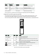
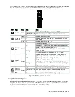
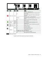
LED Type
Color
State
Status
Power and
sideplane
OK
Green
On
Drawer power on and sideplane hardware functioning properly
Off
Power to drawer off
Drawer
module
fault
Amber
On*
Drawer module fault condition for drawer sideplane or drive
Flashing (1s on, 1s off)
Unit identification (UID) or locate active for drawer sideplane or
drive
Off
Drawer modules functioning properly
Logical
status
Amber
On*
Drive hardware fault condition
Flashing* (3s on, 1s
off)
One or more arrays impacted by drive hardware fault conditions
Off
Drive module hardware functioning properly
Drawer
cable fault
Amber
On*
Cable between rear panel area and drawer fault condition
Off
Cables functioning properly
Drawer
data
activity bar
Green
Flashing (1s on, 1s off)
Segments reflect amount of data activity: greater numbers of
segments reflect greater data activity
Off
No data activity
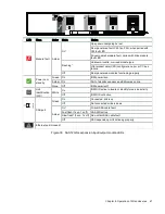
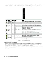
Figure 43 5U84 drawer LED panel
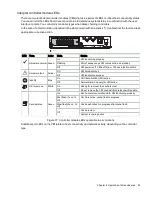
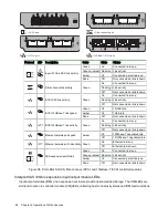
Interpret controller module LEDs
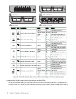
There are two redundant controller modules (CMs) that use a series of LEDs to reflect host connectivity status.
You can monitor the LEDs from the rear panel area to determine system status in combination with the user
interface content. You cannot mix controller types when daisy-chaining controllers.
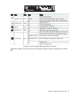
In the case of a fault condition, identified in the state column with an asterisk (*), troubleshoot the fault and take
appropriate corrective action.

