background image

Quantum DX-Series: Optional X520 Network Card Installation Instructions
6-67765-01 Rev C
March 2014

8

Installing the Optional Network Card

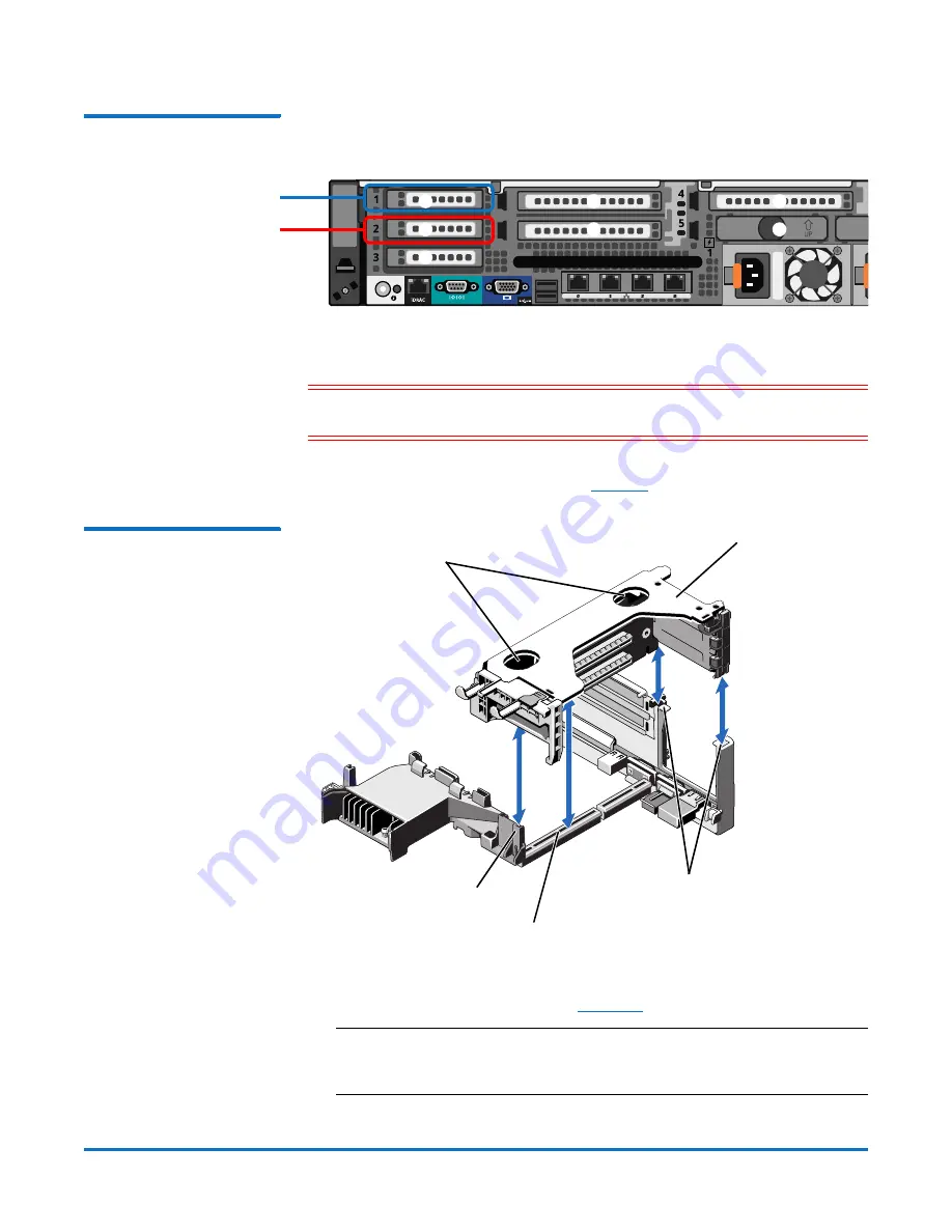
Figure 8  Optional Network 
Card Location

To install the optional network card in the DXi Node:

Caution:

Use appropriate ESD precautions, including the use of a grounding 

strap, when performing this procedure. 

1

Holding the touch points, lift the expansion card riser 1 from the riser 

connector on the system board (see 

Figure 9

).

Figure 9  Removing and 
Installing the Expansion Card 
Riser 1

2

Press the tab to release the expansion card latch and rotate the latch away 

from the expansion card riser (see 

Figure 10

).

Note:

Depending on the DXi model, one or more expansion cards may 

already be installed in expansion card riser 1. Do not remove any 

installed cards from expansion card riser 1.

Supported DXi4xxx models - 

Install network card in slot 1

Node rear

1

2

3

4

5

6

7

Supported DXi6xxx models - 

Install network card in slot 2

Touch points

Expansion card riser 1

Back riser guides

Front riser guide

Expansion card riser 1 

connector

Summary of Contents for Optional i350 Quad Port 1 GbE Card

Page 1: ...configurations Dual port 10 GbE X520 card Provides two 10 GbE SFP Ethernet ports for supported DXi4xxx configurations DXi4700 or higher or for supported DXi6xxx configurations DXi6800 or higher see Fi...

Page 2: ...he System on page 12 Preparing for the Upgrade WARNING To prevent the risk of electrical shock bodily injury or damage to the equipment read all instructions and warnings in the Quantum Products Syste...

Page 3: ...hipping bag or on an antistatic mat Wear anti static wrist bands when unpacking and handling the units and avoid touching connectors and other components Note Dry climates and cold weather heating env...

Page 4: ...lectric shock Caution Use appropriate ESD precautions including the use of a grounding strap when working inside the Node 1 If installed remove the front bezel by lifting the latch on the left side of...

Page 5: ...J slots 6 Lift the Node up and away from the rack and place it on a flat stable surface WARNING The DXi Node including hard drives weighs more than 50 pounds 22 7 kg A minimum of two people are requir...

Page 6: ...ch release lock counterclockwise to the unlocked position see Figure 6 Figure 6 Removing the Node Cover 9 Lift the latch on top of the Node and slide the cover back 10 Grasp the cover on both sides an...

Page 7: ...in three expansion card risers Install the optional network card in the correct slot in expansion card riser 1 see Figure 8 Supported DXi4xxx Models DXi4700 and higher Install the optional network ca...

Page 8: ...the system board see Figure 9 Figure 9 Removing and Installing the Expansion Card Riser 1 2 Press the tab to release the expansion card latch and rotate the latch away from the expansion card riser s...

Page 9: ...e expansion card connector 5 Insert the card edge connector firmly into the expansion card connector until the card is fully seated Make sure the card is inserted into the correct slot Supported DXi4x...

Page 10: ...Replacing the Node Cover 2 Place the cover onto the Node chassis and offset the cover slightly back so that it clears the chassis hooks and lays flush on the chassis 3 Push down the latch to move the...

Page 11: ...arely aligned with the rack as you slide it in 9 If applicable replace the front bezel by inserting the right side of the bezel into the slots on the Node and then snapping the left side of the bezel...

Page 12: ...on the rear of the module displays 99 approximately 120 seconds 2 Press the power button on the front of the Node see Figure 13 Wait for the system to boot This can take up to 30 minutes Figure 13 No...

Reviews: