background image

Determining the DXi4700 Model

Quantum DXi4700 Installation Guide

17

Item

Description

3

Array/Expansion module

4

Accessory Kit

5

Bezel

6

Box

Determining the DXi4700 Model

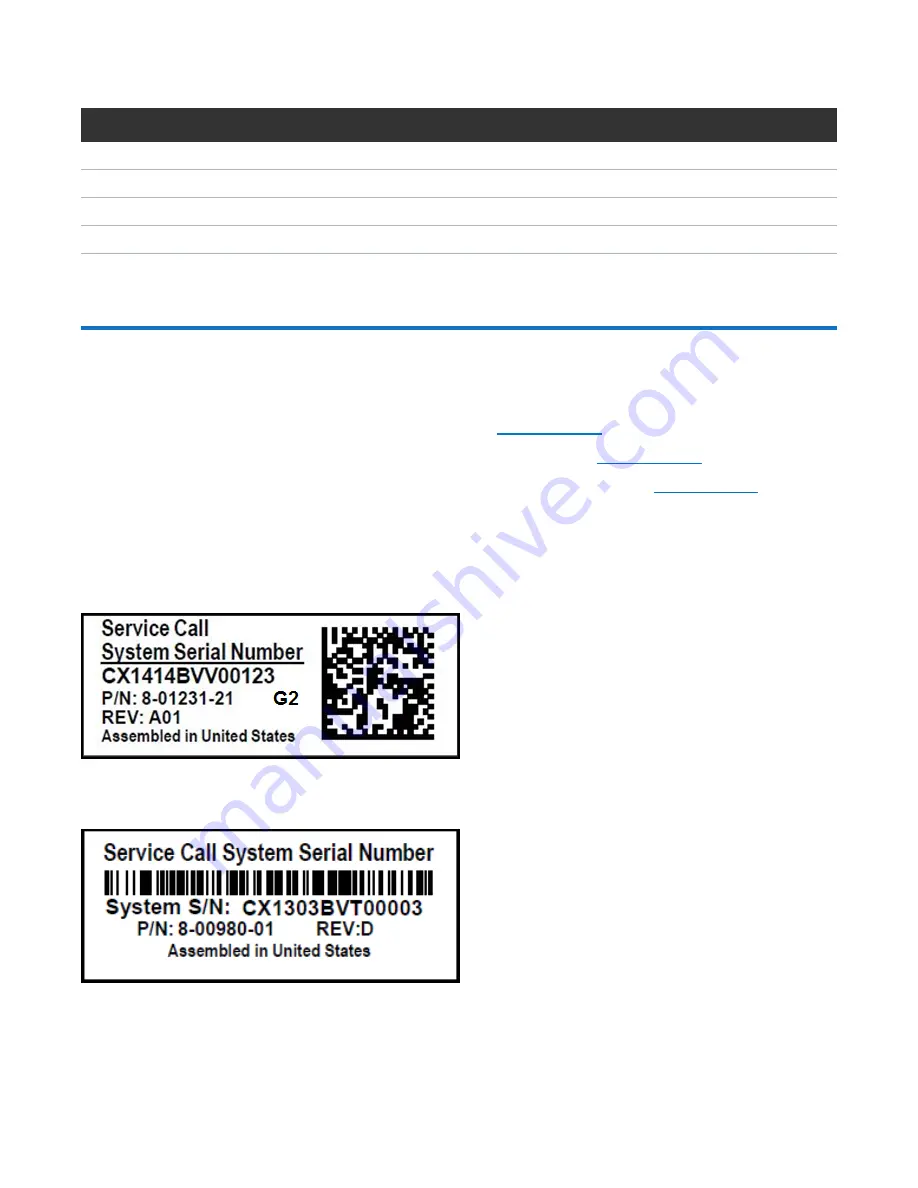
You will need to determine if the DXi system is a DXi4700 G1 or DXi4700 G2. Model information is located 
on the pull-out information tag on the front of the Node (see 

Figure 4 below

)


l

The DXi4700 G2 information tag includes “G2” in the part number (see 

Figure 5 below

).


l

The DXi4700 G1 information tag does not include “G1” in the part number (see 

Figure 6 below

).

Figure 4: 

DXi4700 Information Tag

1. Information Tag


Figure 5: 

DXi4700 G2 Information Tag

Figure 6: 

DXi4700 G1 Information Tag

Summary of Contents for DXi4700

Page 1: ...am Memory Module Installation 78 Troubleshooting 92 Contacting Quantum 94 This guide provides hardware installation and initial system configuration instructions for the Quantum DXi4700 disk backup sy...

Page 2: ...ng a Veeam or DAE configuration require 64 GB system memory 64 GB systems running a Veeam or DAE configuration require 96 GB system memory 96 GB systems running a Veeam or DAE configuration require 12...

Page 3: ...B 135 TB 136 TB 96 GB 3 8U 1 TB 1 000 000 000 000 bytes Usable storage capacity for installed Array or Expansion modules can be upgraded at any time after purchase in increments of 6TB 8TB and 18TB St...

Page 4: ...stem memory 64 GB systems running a Veeam or DAE configuration require 96 GB system memory 96 GB systems running a Veeam or DAE configuration require 128 GB system memory 1 TB 1 000 000 000 000 bytes...

Page 5: ...equirements Review the DXi4700 Site Planning Guide to ensure that your site meets the installation requirements for the DXi4700 Rack Space Requirements Table 1 below contains the rack requirements for...

Page 6: ...The installation site must have the following environmental conditions Humidity l DXi4700 G1 20 to 80 non condensing with a maximum humidity gradient of 10 per hour l DXi4700 G2 10 to 80 non condensin...

Page 7: ...omplete the DXi4700 system installation the latest version of DXi software is mandatory If the DXi will not have Internet connectivity manually download a copy of the latest DXi software upgrade file...

Page 8: ...the number of the box and the total number of boxes in the shipment for example box 1 of 3 MAKE SURE THAT YOU HAVE ALL BOXES IN THE SHIPMENT BEFORE YOU BEGIN THE INSTALLATION Table 1 on the next page...

Page 9: ...X540 10 GBase T Card 1 Unpacking the DXi4700 on page 12 2 Determining the DXi4700 Model on page 17 3 Installing Components in the DXi4700 Node on page 18 a Opening the Node Cover on page 21 b Installi...

Page 10: ...he DXi4700 on page 12 2 Determining the DXi4700 Model on page 17 3 Installing the Node Hard Drives on page 18 4 Installing Components in the DXi4700 Node on page 18 a Opening the Node Cover on page 21...

Page 11: ...ng the Node Cover on page 21 b Installing the Memory Modules on page 26 c Installing the H810 H830 RAID Controller on page 30 d Installing the X520 Network Card on page 33 e Installing the X540 Networ...

Page 12: ...s 26 8 kg respectively A minimum of two people are required to lift either chassis Unpacking the DXi4700 Node The box containing the DXi4700 Node contains the following items Item Description Rack mou...

Page 13: ...Unpacking the DXi4700 Quantum DXi4700 Installation Guide 13 Figure 1 Unpacking the DXi4700 Node Item Description 1 Bezel key taped to back 2 Accessory Kit 3 Rack mount rails...

Page 14: ...ents may ship in separate boxes along with the rest of the system see DXi4700 Installation Overview on page 8 l 4 TB hard drive 6 l 4 GB Memory Module 8 or 16 l H810 RAID Controller DXi4700 G1 l H830...

Page 15: ...contains the following items l Rack mount rails o Cable management straps l Accessory kit which includes the following o C13 to C14 power cord 2 o North American power cord 2 o SAS interconnect cable...

Page 16: ...Unpacking the DXi4700 Quantum DXi4700 Installation Guide 16 Figure 3 Unpacking the DXi4700 Expansion Module Item Description 1 Rack mount rails 2 Foam...

Page 17: ...4700 G1 or DXi4700 G2 Model information is located on the pull out information tag on the front of the Node see Figure 4 below l The DXi4700 G2 information tag includes G2 in the part number see Figur...

Page 18: ...540 Network Card on page 38 l Closing the Node Cover on page 41 Installing the Node Hard Drives The Node has a total of 12 hard drive slots and ships from the factory with 6 hard drives 4 TB each pre...

Page 19: ...hard drives 4 TB each in Node hard drive slots 6 11 Figure 7 Node Hard Drive Locations 1 2 3 4 5 6 7 8 9 10 11 12 0 1 2 3 4 5 6 7 8 9 10 11 Item Description 0 HDD Slot 0 Do not remove 1 HDD Slot 1 Do...

Page 20: ...and press the release button see Figure 8 below b Slide the hard blank out until it is free of the hard drive slot Figure 8 Removing a Node Hard Drive Blank 1 2 Item Description 1 Hard drive blank 2...

Page 21: ...cover WARNING The DXi4700 G1 Node and Expansion module JBOD weigh 61 0 pounds 27 7 kg and 62 6 pounds 28 4 kg respectively A minimum of two people are required to lift either chassis WARNING The DXi4...

Page 22: ...ion Guide 22 Figure 10 Node Power Button 1 Power Button 4 On the Node cover rotate the latch release lock counterclockwise to the unlocked position see Figure 11 below Figure 11 Removing the Node Cove...

Page 23: ...he cover on both sides and carefully lift the cover away from the Node 7 a Remove the cooling shroud by holding the touch points and lifting the shroud away from the Node see Figure 12 below Figure 12...

Page 24: ...bly 1 2 3 4 5 6 Item Description 1 Cooling fan assembly 2 Cooling fan 3 Release lever 2 4 Guide pin on the system board 2 5 Cooling fan connector 6 6 Guide pin on the chassis 6 9 Lift the cooling fan...

Page 25: ...DXi4700 Node Quantum DXi4700 Installation Guide 25 Figure 14 Inside the DXi4700 Node 1 0 2 3 1 0 2 3 1 2 3 4 5 Item Description 1 Cooling shroud 2 Memory modules 3 Expansion card riser 1 l Optional X...

Page 26: ...mory modules must be installed in the correct sockets in order for the system to function properly see Figure 15 on the next page WARNING DAE and Veeam Memory Configurations For DXi4700 systems with a...

Page 27: ...s in slots A1 A4 and B1 B4 white sockets l Install 8 x 4 GB memory modules in slots A5 A8 and B5 B8 black sockets l Install 8 x 4 GB memory modules in slots A9 A12 and B9 B12 green sockets Figure 15 N...

Page 28: ...ry blanks are recyclable Figure 16 Installing a Memory Module 1 2 3 Item Description 1 Memory module 2 Ejector latch 3 Socket alignment tool 2 Align the memory module s edge connector with the alignme...

Page 29: ...lide the cooling fan assembly into the chassis c Lock the cooling fan assembly into the chassis Figure 17 Replacing the Cooling Fan Assembly 6 Replace the cooling shroud a Align the tabs on the coolin...

Page 30: ...is required for 45 TB and larger configurations see Table 3 below Install the provided H810 H830 RAID controller card in PCIe slot 6 located in expansion card riser 3 see Figure 19 below for DXi4700 G...

Page 31: ...the H810 or H830 RAID controller card in the DXi4700 Node Caution Use appropriate ESD precautions including the use of a grounding strap when performing this procedure 1 Lift the blue expansion card...

Page 32: ...d 3 Metal slot cover 4 Expansion card connector 5 Expansion card riser 3 2 Remove the metal slot cover from slot 6 by sliding it out of the slot 3 Holding the H810 or H830 card by its edges position t...

Page 33: ...following locations l DXi4700 G1 in PCIe slot 1 located in expansion card riser 1 see Figure 22 below l DXi4700 G2 in PCIe slot 4 located in expansion card riser 2 see Figure 23 on the next page A DX...

Page 34: ...rd Option s 1 Install X520 10 GbE network card in slot 4 DXi4700 G1 Installing the X520 Network Card To install the X520 10 GbE network card in the DXi4700 Node Caution Use appropriate ESD precautions...

Page 35: ...alling the Expansion Card Riser 1 1 2 3 4 5 Item Description 1 Touch points 2 Expansion card riser 1 3 Front riser guide 4 Expansion card riser 1 connector 5 Back riser 2 Press the tab to release the...

Page 36: ...ng the X520 card by its edges position the card so that the card edge connector aligns with the expansion card connector 5 Insert the card edge connector firmly into the expansion card connector until...

Page 37: ...twork card in the DXi4700 G2 Node Caution Use appropriate ESD precautions including the use of a grounding strap when performing this procedure 1 Lift the expansion card latch out of the slot see Figu...

Page 38: ...GbE network card Installing the X540 Network Card The X540 network card provides two 10 GBase T Ethernet ports and is an available option for all DXi4700 configurations see Table 5 below The 10 GBase...

Page 39: ...rd in slot 4 To install the X540 10 GBase T network card in the DXi4700 Node Caution Use appropriate ESD precautions including the use of a grounding strap when performing this procedure 1 Lift the ex...

Page 40: ...Metal slot cover 4 Expansion card connector 5 Expansion card riser 2 2 Remove the metal slot cover from slot 4 by sliding it out of the slot 3 Holding the X540 card by its edges position the card so...

Page 41: ...h on the cover see Figure 29 below Figure 29 Replacing the Node Cover 1 2 3 Item Description 1 Latch release lock 2 Latch 3 Node cover 2 Place the cover onto the Node chassis and offset the cover slig...

Page 42: ...e Components in the Rack Component Installation Recommendations To make it easier to correctly cable the system and for safety reasons follow these recommendations when installing the DXi4700 system i...

Page 43: ...5 inch 12 7 mm 0 5 inch WARNING If the rack is empty at the time of installation do NOT install the DXi4700 chassis too high in the rack The weight of the chassis may cause the rack to become top heav...

Page 44: ...are required to lift the chassis To lift the chassis use the slots in the packing foam to place your hands under the sides of the chassis Caution Before proceeding ensure that all hard drive latches a...

Page 45: ...of the module and install the end cap with the drive numbers to the right of the module Note To remove the Expansion module remove the screws and slide the module out of the rack Figure 33 DXi4700 Ex...

Page 46: ...lign each back end piece in the bottom and top holes of the desired U spaces 3 Engage the back end of the rail until it fully seats on the vertical rack flange and the latch clicks into place Repeat t...

Page 47: ...ssis If they have been removed for any reason during or after the installation you must install the hard drives in the same position in which they were removed 1 Pull the inner slide rails out of the...

Page 48: ...DXi4700 Installation Guide 48 Figure 35 Node Installation 1 2 3 4 5 Item Description 1 Rear rail standoffs 2 Rear rail J slots 3 Slide release lock button 4 Lock lever 5 Inner slide rails Cabling the...

Page 49: ...2 Connecting the DXi4700 G2 Expansion Modules JBODs Node JBOD 1 JBOD 2 JBOD 3 SAS port 1 left Primary SAS In port 1 top SAS port 2 right Secondary SAS In port 1 bottom Primary SAS port 2 top Primary S...

Page 50: ...y and secondary AC power source using the provided power cables see Figure 39 on page 53 Use the attached straps to secure the power cords to the chassis Note Quantum recommends connecting each power...

Page 51: ...Installing the DXi4700 System in the Rack Quantum DXi4700 Installation Guide 51 Figure 37 DXi4700 G2 SAS Cabling...

Page 52: ...Installing the DXi4700 System in the Rack Quantum DXi4700 Installation Guide 52 Figure 38 DXi4700 Fibre Channel Cabling VTL PTT Configurations Only...

Page 53: ...al Configuration Before the DXi4700 is operational you must configure the system through the remote management console You must also configure your backup software Configuring the DXi4700 consists of...

Page 54: ...hes on the back of each Expansion module see Figure 40 below Wait 30 seconds for the Expansion modules to initialize Verify on the front panel that the modules have power and there were no hard drive...

Page 55: ...ndows 7 on the computer The steps might be different if you are using another operating system a Access the Network Connections control panel To do this press the Windows key on the keyboard type view...

Page 56: ...Caution Before changing the IP address information write down the original settings This will be used later to reset the network configuration l IP address 10 1 1 2 l Subnet mask 255 255 0 0 e Click O...

Page 57: ...ork settings on the computer are correct Wait 10 minutes then try again If the Login window still does not display contact Quantum Customer Support Contact information is located on the last page of t...

Page 58: ...ad the information about the wizard and then click Next to continue The License Agreement page displays see Figure 46 below Figure 46 Getting Started Wizard License Agreement 3 Select the I have read...

Page 59: ...sword 5 Create a new password for the Service SSH ServiceLogin user account a Enter a New Password Additional Information l The Service SSH password can be up to 20 characters Alphanumeric characters...

Page 60: ...those below Work with your network administrator to determine the correct settings for integrating the DXi4700 into your company s network If you set up the DXi4700 using the example below you can alw...

Page 61: ...r General enter the following network information as provided by your network administrator a Enter the Hostname used to identify the DXi4700 system The Hostname cannot be blank and must contain only...

Page 62: ...targets and other information 8 Under IP Address Configuration Bonding Details configure each Ethernet port as a separate network device a If necessary click the Show link to show the bonding details...

Page 63: ...guration Routing Details unless directed by your network administrator Note If the DXi needs to communicate with another subnet that is not reachable using the default gateway a route must be added un...

Page 64: ...e DNS IP address above Otherwise you must specify the IP address of the timeserver pool For more information see the Quantum DXi4700 User s Guide 14 In the Timezone drop down box select the time zone...

Page 65: ...7 Review the settings you selected to make sure they are correct If necessary click Previous to return to a previous step to make changes 18 After you have confirmed all settings click Finish A messag...

Page 66: ...ion To complete the software upgrade 1 On the service laptop open a supported Web browser type 10 1 1 1 in the Address box and press Enter The Login window displays see Figure 51 on the next page Addi...

Page 67: ...gure 51 Login Window 2 On the Login window select Administrator type the password you created in the Getting Started Wizard and click Login The Upload New DXI Software Upgrade File page displays see F...

Page 68: ...to access the Internet If the DXi cannot access the Internet a link back to the Getting Started Wizard Network page appears see Figure 53 below Note Resetting network settings in the Getting Started...

Page 69: ...management console displays correctly Manually upload a software upgrade file This option allows you to upload and install a software upgrade file on the DXi4700 Use this upgrade method if the DXi ca...

Page 70: ...Figure 55 below Figure 55 Install Software Upgrade File 6 Click Install The Software Upgrade Utility displays see Figure 56 below Figure 56 Software Upgrade Utility 7 Click Check Now to check for avai...

Page 71: ...ng Ethernet cables or making configuration changes it is normal for the Admin Alert indicator to display on the remote management console Caution CAT6 Ethernet cables can be damaged when tightened wit...

Page 72: ...your account sales manager to purchase additional new bezels Install the protective bezel on the front of the DXi4700Node The bezel snaps into place on the front of the Node to prevent the removal of...

Page 73: ...ft side of the bezel into place Note To remove the bezel lift the latch on the left side of the bezel Caution The Expansion module bezel may interfere with door operation on some rack models In this c...

Page 74: ...ndows on a computer with Internet access Note During this procedure you can copy and paste required numbers between these two windows a In one browser navigate to the Utilities License Keys page in th...

Page 75: ...ed Feature page returns a storage capacity key 3 Switch to the Utilities License Keys page in the DXi remote management console see Figure 61 on the previous page 4 Enter the license key in the New Ke...

Page 76: ...ext page l Operating the DXi4700 on the next page l Installing Additional DAE Veeam Memory Modules on page 78 Configuring Email Reports Quantum recommends enabling Email Reports after you install your...

Page 77: ...OST Wizard NAS and Multi Protocol configurations only Helps you configure the DXi to present its storage as one or more OST OpenStorage storage servers for use with a backup application Replication Wi...

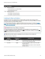
Page 78: ...below DAE Veeam Memory Module Installation For DXi4700 systems with a DAE or Veeam configuration the installation of additional memory modules is required Memory modules must be installed in the corr...

Page 79: ...the Node Cover To open the DXi4700 Node cover 1 Set the Node on a flat stable surface 2 Make sure that no cables power Ethernet Fibre Channel or SAS are connected to the Node 3 Press and hold the powe...

Page 80: ...cription 1 Latch release lock 2 Latch 3 Node cover 5 Lift the latch on top of the Node and slide the cover back 6 Grasp the cover on both sides and carefully lift the cover away from the Node 7 a Remo...

Page 81: ...Module Installation Quantum DXi4700 Installation Guide 81 Figure 68 Removing the Cooling Shroud 1 1 Cooling shroud 8 Remove the cooling fan assembly by lifting the release levers upwards see Figure 69...

Page 82: ...y 1 2 3 4 5 6 Item Description 1 Cooling fan assembly 2 Cooling fan 3 Release lever 2 4 Guide pin on the system board 2 5 Cooling fan connector 6 6 Guide pin on the chassis 6 9 Lift the cooling fan as...

Page 83: ...nstallation Quantum DXi4700 Installation Guide 83 Figure 70 Inside the DXi4700 Node 1 0 2 3 1 0 2 3 1 2 3 4 5 Item Description 1 Cooling shroud 2 Memory modules 3 Expansion card riser 1 l Optional X52...

Page 84: ...Table 1 DAE or Veeam Memory Configurations DXi4700 Configuration Total System Memory Actions to Take 5 27 TB 64 GB 1 Leave the pre installed modules in slots A1 A4 and B1 B4 white sockets 2 Install 8...

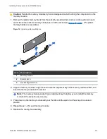
Page 85: ...e use of a grounding strap when performing this procedure Caution Handle the memory modules by the card edges and avoid touching the components on the memory module 1 Remove the plastic memory blank o...

Page 86: ...socket Note The memory module socket has an alignment key that allows you to install the memory module in the socket in only one way 3 Press down on the memory module with your thumbs until the eject...

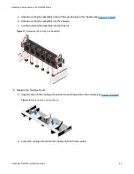
Page 87: ...e cooling shroud with the securing slots on the chassis see Figure 74 below Figure 74 Replacing the Cooling Shroud b Lower the cooling shroud into the chassis until it is firmly seated Note For proper...

Page 88: ...Latch 3 Node cover 2 Place the cover onto the Node chassis and offset the cover slightly back so that it clears the chassis hooks and lays flush on the chassis 3 Push down the latch to move the cover...

Page 89: ...e lock button 4 Lock lever 5 Inner slide rails 6 Locate the rear rail standoff on each side of the system and lower them into the rear J slots on the slide assemblies 7 Rotate the Node downward until...

Page 90: ...front panel that the modules have power and there were no hard drive failures Drive status indicator on hard drive blinks amber four times per second Figure 77 Expansion Module Power Switches 1 Power...

Page 91: ...antum DXi4700 Installation Guide 91 For complete DAE Veeam installation and configuration instructions please refer to the DAE Installation Guide and Veeam Installation Guide on the DXi4700 Documentat...

Page 92: ...00 and that the network settings on the laptop are properly configured see Accessing the Remote Management Console on page 54 Make sure to wait at least 30 minutes after turning on the system before a...

Page 93: ...wer switches on the back of each Expansion module 4 Make sure all hard drives are inserted completely and all hard drive latches are closed see Installing the Node Hard Drives on page 18 5 Make sure a...

Page 94: ...ht law Making copies or adaptations without prior written authorization of Quantum Corporation is prohibited by law and constitutes a punishable violation of the law Artico Be Certain and the Q bracke...

Reviews: