background image

Manual for WinneX 3E

Chapter 1

Introduction

Chapter 1

Chapter 1

Introduction

Overview

The WinneX 3E green mainboard utilizes the Intel first generation integrated graphics chipset

—   Intel

®

 810E Chipset, providing a fully compatible, high performance and cost-effective PC/

microATX platform. The new  integrated technologies, together w ith the softw are configurable

AC’97 audio and modem system give customers an advanced, multimedia solution at an

extremely low  price. It provides 66/100/133MHz system bus support for all Intel Pentium

®

 III,

Pentium

®

 II, and Celeron

T M

 Slot1 processors. SDRA Ms are supported up to 512MB. It also

provides advanced features such as Wake-on-LAN, Wake-on-Modem and Keyboard Pass-
w ord Pow er- on functions. Suspend to RAM, the optimal implementation of the Advanced

Configuration and Pow er Interface (ACPI) specification, makes the PC’s pow er consump-
tion drop to the low es t possible level and enable quick w akeup. ManageEasy, our system
management application is also supplied to enable remote monitoring and c onfiguration of

the system.

Flexibility in Designing Cost-effective System

The Intel

®

 810E Chipset is a high-integration chipset w hic h consists  of a Graphics and

Memory Controller HubE (GMCHE) Host Bridge and an I/O Controller  Hub (ICH) Bridge. The

Intel

®

 810E Chipset System provides added flexibility in designing cost-effective solutions.

Intel

®

 810E

:  GMCHE (Intel

®

 82810E) + ICH (Intel

® 

82801AA)

Added features:

Includes 4MB, 32-bit 100/133MHz SDRAM Display Cache.

Supports Ultra ATA/66.

Key Features

Form  factor

MicroATX form factor of 244mm x 195mm.

Microprocessor

Supports Intel

®

  Pentium

®

 III Processors at 533/600/667/733MHz and future processors

w ith 133MHz bus speed.

Supports Intel

®

  Pentium

®

 III Processors at 450/500/550/600/700MHz and future proces-

sors w ith 100MHz bus speed.

Supports Intel

®

  Pentium II

®

 Processors at 300/350/400/450MHz and future processors

w ith 100MHz bus speed.

Supports Intel

®

  Pentium

®

 II Processors at 233/266/300/333MHz and future processors

w ith 66MHz bus speed.

Summary of Contents for WinneX 3E

Page 1: ...l and enable quick w akeup ManageEasy our system management application is also supplied to enable remote monitoring and configuration of the system Flexibility in Designing Cost effective System The Intel 810E Chipset is a high integration chipset w hich consists of a Graphics and Memory Controller HubE GMCHE Host Bridge and an I O Controller Hub ICH Bridge The Intel 810E Chipset System provides ...

Page 2: ...g four IDE devices including IDE hard disks and CD ROM drives l Supports up to PIO Mode 4 timing l Supports Ultra ATA 33 Synchronous DMA modes transferring data up to 33MB s l Supports Ultra ATA 66 Synchronous DMA modes transferring data up to 66MB s l Integrated 16x32bit buffer for IDE PCI Burst Transfers Onboard I O l Winbond W83627HF LPC I O chip l One floppy port supporting up to tw o 3 5 or 5...

Page 3: ...t applications such as LDCM LANDesk Client Manager or QDI s ManageEasy manufacturing option l Provides onboard 3 3V regulator to support ATX pow er supply w ithout 3 3V output l System status resumes after AC pow er failure l Supports QDI s innovations such as SpeedEasy RecoveryEasy etc l Protects the system BIOS from being attacked by severe virus such as CIH l Supports Suspend to RAM BIOS l Lice...

Page 4: ...e nd to RAM Suspend to RAM is a cost eff ective optimal implementation of the Advanced Configu ration and Pow er Interface ACPI 1 0 specification w hich makes a PC s pow er con sumption drop to the low est possible level and enables quick w akeup When the system is in Suspend to RAM status the system context is maintained in system memory the system consumes only a small fraction of the pow er use...

Page 5: ...e pow er button through the Wake on LAN Wake on Modemfunction or RTC Alarm If the keyboard passw ord pow er on func tion is enabled the keyboard passw ord should be used to w ake up the systeminstead of pushing the pow er button Ultra ATA 66 According to the previous ATA IDE hard drive data transfer protocol the signaling w ay to send data w as in synchronous strobe mode by using the rising edge o...

Page 6: ...e host then the host retries the command containing the CRC error Ultra ATA 66 technology increases both performance and date integrity How ever there are basically five requirements for your system to run in Ultra ATA 66 mode 1 The system board must have a special Ultra ATA 66 detect circuit such as WinneX 3E mainboard 2 The system BIOS must also support Ultra ATA 66 3 The operating system must b...

Page 7: ...erwise your mainboard and expansion cards might be seriously damaged External Connectors PS 2 Keyboard Connector PS 2 Mouse Connector PS 2 keyboard connector is for the usage of PS 2 keyboard If using a standard AT size keyboard an adapter should be used to fit this connector PS 2 mouse connector is for the usage of PS 2 mouse USB1 USB2 Tw o USB ports are available for connecting USB devices Paral...

Page 8: ... for voice input The Speaker out jack allow s you to connect speakers or headphones f or audio output from the internal amplifier The MIDI Joystick connector allow s you to connect a game joystick or a MIDI device ATX Power Supply Connector Power Switch POWER Be sure to connect the pow er supply plug to this connector in its proper orientation The pow er sw itch POWER should be connected to a mome...

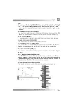
Page 9: ...or can be connected to the speaker on the case Power LED Connector PWR_LED The pow er LED has tw o status When the system is in pow er off status the LED is off When the system is pow ered up the LED is on The connector has an orientation Key Lock Connector KEY_L The connector can be connected to the keyboard lock sw itch on the case for locking the keyboard ACPI LED Connector GREEN_LED The A CPI ...

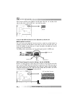
Page 10: ...atically turned of f after the system enters sus pend mode Wake Up On LAN WOL Through the Wake Up On LAN f unction a w ake event occurring from the netw ork can w ake up the system If this function is to be used please be sure an ATX 2 01 pow er supply of w hich 5VSB line is capable of delivering 720mA and a LA N adapter w hich supports this function is used Then connect this header to the relevan...

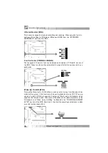
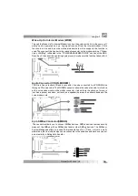
Page 11: ...ector CDLIN MODEM CDLIN is a Sony standard CD audio connector it can be connected to a CD ROM drive through a CD audio cable The MODEM connector allow s the onboard audio to interface w ith a voice modem card w ith a similar connector It also allow s the sharing of mono_in such as a phone and mono_out such as a speaker betw een the onboard audio and the voice modem card 4 pin SMBus Connector SMBUS...

Page 12: ...em Riser Interface Connector AMR The AMRInterface Connector isthe interface betw een the mainboard and the Audio Modem Riser card The connector provides allnecessary signals w hich supports several different configurations of audio and modem in the system such as audio and modem on the Riser audio on the mainboard and modem on the Riser or no audio w ith modem on the Riser WinneX 3E mainboard prov...

Page 13: ...1 pin2 connected and to represent pin2 pin3 connected For default jumper settings please refer to the follow ing table JFS0 1 2 Auto JKB 1 2 Enable KB Pow er on JFS1 1 2 Auto JUSB 1 2 Enable USB Wake Up JCC 2 3 Normal Status JSB Closed Connect PCI 3 3Vsb JSD 2 3 Enable A udio JAV Open Enable Flash BIOS Overclocking Jumper Setting JFS0 JFS1 Jumpers labeled JFS0 and JFS1 are located on the mainboard...

Page 14: ...w er in CPU SpeedEasy Setup in AWARD BIOS CMOS Setup We do not guarantee the overclocking system to be stable Clear CMOS JCC If you want to clear CMOS unplug the AC pow er supply first close JCC pin1 pin2 once set JCC back to the normal status w ith pin2 pin3 connected then pow er on the system Enable Disable On board Audio CODEC JSD If you w ant to use the on board audio CODEC set JSD w ith pin2 ...

Page 15: ...power up your system by the keyboard or the power button 3 If you encounter the above problems clear CMOS and se t the jumper and BIOS option again PCI 3 3VSB Voltage Jumper JSB Setting JSB open can disconnect the 3 3VSB voltage to PCI slots This can prevent the mainboard from being damaged if you add or remove expansion cards w ithout unpluging the AC pow er supply How ever if you w ant to use th...

Page 16: ...ked by serious virus such as CIH virus Setting the jumper JAV as open default meanw hile disabling the Flash Write Protect item in AWARD BIOS CMOS Setup allow s you to flash the BIOS to the flash ROM in FWH The DMI Desktop Management Interface system information such as the CPU type speed memory size and expansion cards w ill be detected by the onboard BIOS and stored in the flash ROMin FWH Whenev...

Page 17: ...der Window s95 98 English version run ChipDrv Intel Whitney Display w in9x Graph ics Setup exe for installation Under Window s 95 98 Chinese version the VGA driver should be installed manually from the Display Proper ties Window Locate the directory to ChipDrv Intel Whitney Display w in9x Graphics Win9x w hen prompted Please refer to README TXT in the directory ChipDrv Intel Whitney Display w in9x...

Page 18: ...ing w ith the computer s development the system of the computer w ill become more and more complex at the same time the control of computer s hardw are w ill be strengthened Today it is possible to monitor and manage your complex hardw are from Window s 9X and Window s NT QDI ManageEasy is a system tool like a bridge betw een the complex hardw are and OS used to access hardw are status and to exec...

Page 19: ...mpt under DOS6 xx or Window s 9x environment 2 Copy A WDFLASH EXE version 7 07 from the directory Utility located on QDI Mainboard Utility CD onto your new bootable diskette 3 Dow nload the updated BIOS file from the Website http w w w qdigrp com Please be sure to dow nload the suitable BIOS file for your mainboard 4 Uncompress the f ile dow nload copy the BIOS file xx bin onto the bootable disket...

Page 20: ...leven setup functions and tw o exit choices Use the arrow keys to select among the items and press the Enter key to accept or enter the sub menu Figure 1 Main Menu Load Optimized Defaults The Optimized Defaults are common and efficient It is recommended users load the optimized defaults first then modify the needed configuration settings Standard CMOS Features Setup The basic CMOS settings include...

Page 21: ...of 2 IDE channels installed in the computer system There are three choices provided for the Enhanced IDE BIOS None Auto and User None meansno HDDis installedor set Auto meansthe systemcan auto detectthe harddisk w hen booting up by choosing user the related information should be entered regardingthe follow ing items Enter the information directly from the keyboard and press Enter CYLS number of cy...

Page 22: ...ber into its ow n physical address inside the HDD The maximum HDD size supported by LBA mode is 8 4 Gigabytes LARGE mode Some IDE HDDs contain more than 1024 cylinder w ithout LBA support in some cases users do not w ant LBA The Aw ard BIOS provides another alternative to support these kinds of HDD BIOS tricks DOS or other OS into divising the number of cylinders isless than 1024 by dividing it by...

Page 23: ... stop and you w ill be prompted All But Keyboard The system boot w ill not stop for a keyboard error but it w ill stop for all other errors All But Diskette The system boot w ill not stop for a disk error but it w ill stop for all other errors All But Disk Key The systemboot willnot stop for a keyboard or disk error but it w ill stop for all other errors Memory This is a Display Only Category dete...

Page 24: ... Jumper Emulation This item is only for users w ho understand all the CPU parameters i e system bus frequency 66MHz and multiplication of processor core frequency for system bus frequency x2 5 x3 x3 5 x4 x4 5 x5 x5 5 x6 x6 5 x7 x7 5 x8 133MHz 66x2 Selects the CPU speed according to your CPU 166MHz 66x2 5 brand and type 533MHz 66x8 200MHz 100x2 250MHz 100x2 5 800MHz 100x8 BIOS Description ...

Reviews: