background image

I

NSTALLING

 H

ARDWARE

I

NSTALLING


THE

 M

IDPLANE

 2-14

Installing the Midplane

Make sure the enclosure is on a clean work surface before starting this procedure.

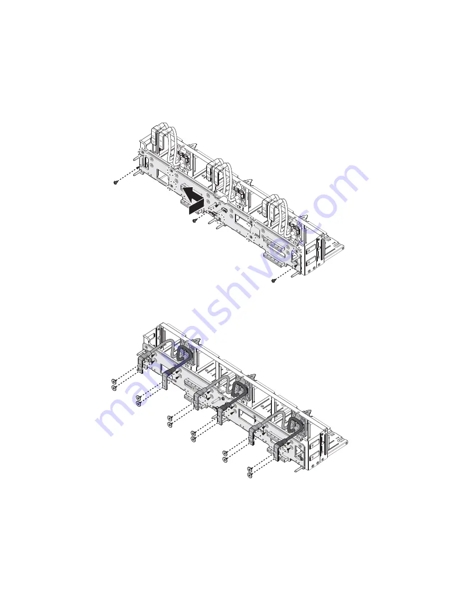
1. Align the midplane board with the standoffs on the rear assembly. 

2. Slide the midplane from right to left to lock the midplane on the rear assembly.

Figure 2-19.

Installing the midplane

3. Secure the midplane and rear assembly with the provided screws.

Figure 2-20.

Installing the midplane

Summary of Contents for Rackgo X Series F03A

Page 1: ...Version 1 0 0 Rackgo X Series F03A Superior Serviceability 4 x Compute Node 2U Server Technical Guide ...

Page 2: ... this document is subject to change without notice The manufacturer makes no representations or warranties with respect to the contents hereof and specifi cally disclaims any implied warranties of merchantability or fitness for any particular pur pose Furthermore the manufacturer reserves the right to revise this publication and to make changes from time to time in the content hereof without oblig...

Page 3: ...iew 1 4 Node Overview 1 5 Node Front View 1 6 LED Definitions 1 7 Mainboard LEDs 1 7 LAN Port LEDs 1 8 Fan LED 1 9 Installing Hardware Safety Measures 2 1 Sled Tray 2 2 Releasing the Sled Tray 2 2 Securing a Sled Tray 2 2 Air Duct 2 4 Removing an Air Duct 2 4 Installing an Air Duct 2 5 Fan Module 2 6 Removing a Fan Module 2 6 Installing a Fan Module 2 9 ...

Page 4: ...oving an iBBU 2 20 Installing an iBBU 2 21 Processor Heat Sinks 2 23 Removing a Processor Heat Sink 2 23 Installing a Processor Heat Sink 2 24 Processors 2 26 Removing a Processor 2 26 Installing a Processor 2 27 Interposer Board 2 29 Removing the Interposer Board 2 29 Installing the Interposer Board 2 29 Mezzanine Board optional 2 31 Removing the Mezzanine Board 2 31 Installing the Mezzanine Boar...

Page 5: ...nds 3 2 Menu Selection Bar 3 3 Server Platform Setup Utility Screens 3 4 Main Screen 3 4 Advanced Screen 3 5 PCI Subsystem Settings 3 7 WHEA Configuration 3 8 CPU Configuration 3 8 Runtime Error Logging 3 13 SATA Configuration 3 14 SAS Configuration 3 15 USB Configuration 3 16 Super IO Configuration 3 16 H W Monitor 3 18 Onboard Device Configuration 3 18 Serial Port Console Redirection 3 19 Chipse...

Page 6: ...on Update 3 42 BIOS Setting Utility 3 43 BIOS Recovery 3 43 BIOS Revision 3 44 Clear CMOS 3 47 Clear Password 3 48 Server Management 3 49 Console Redirection 3 49 Serial Configuration Settings 3 49 Keystroke Mapping 3 49 Reset 3 50 Limitations 3 50 Interface to Server Management Optional 3 51 Network BIOS Support 3 51 PXE Boot 3 51 Checkpoints 3 51 Debug Header 3 51 Standard Checkpoint 3 52 ACPI A...

Page 7: ...board and Mouse Emulation 4 8 Keyboard LED and Status Synchronization 4 9 System Maintenance 4 9 Firmware Management Options 4 9 Firmware Upgrade Status 4 10 Security 4 10 Authentication 4 10 Local User Data Base 4 10 Encryption 4 11 AES for commands of KVM Keyboard Mouse over IP 4 11 Hardware Cryptographic Engines 4 11 Miscellaneous 4 11 KVM and Discovery Occupy TCP and UDP Port on network 4 11 I...

Page 8: ... not ready or server does not see hard disk drive 6 2 HDD SATA failure 6 2 Motherboard No Boot 6 2 Motherboard fails single bit ECC Errors 6 3 Motherboard fails multiple bit error or rebooting 6 4 Motherboard fails 1G Ethernet port 6 4 Motherboard fails for PXE 10G Mellanox 6 4 Motherboard rebooting 6 4 Fan failure 6 4 Hardware Failure Troubleshooting Matrix 6 5 SOL 6 7 Regulatory and Compliance I...

Page 9: ...ONTENTS VIII VCCI Japan 7 2 BSMI Taiwan 7 2 Regulated Specified Components 7 2 Restriction of Hazardous Substances RoHS Compliance 7 3 End of Life Product Recycling 7 3 Product Regulatory Compliance Markings 7 4 ...

Page 10: ...ons and the names of the folders menus programs and files Enter type face denotes keyboard keys WARNING Warning information appears before the text it references and should not be ignored as the content may prevent damage to the device CAUTION CAUTIONS APPEAR BEFORE THE TEXT IT REFERENCES SIMILAR TO NOTES AND WARNINGS CAUTIONS HOWEVER APPEAR IN CAPITAL LETTERS AND CONTAIN VITAL HEALTH AND SAFETY I...

Page 11: ...ed and serviced only by technically qualified persons You must adhere to the guidelines in this guide and the assembly instructions in related chapters to ensure and maintain compliance with existing product certifications and approvals Use only the described regulated components specified in this guide Use of other products components will void other regulatory approvals of the product and may re...

Page 12: ... properly grounded wall outlet Provided with sufficient space to access the power system because they serve as the product s main power disconnect The enclosure is designed to carry only the weight of the system sled Do not use this equipment as a workspace Do not place additional load onto any equipment in this system Do not move racks by yourself Due to the height and weight of the rack a min im...

Page 13: ... POWER SOURCE CAUTION TO AVOID RISK OF ELECTRIC SHOCK DISCONNECT ALL CABLING FROM THE SYSTEM AND REMOVE THE SYSTEM FROM THE RACK CAUTION TO AVOID PERSONAL INJURY OR PROPERTY DAMAGE THE FOLLOWING SAFETY INSTRUCTIONS APPLY WHENEVER ACCESSING THE INSIDE OF THE PRODUCT Disconnect from the power source by removing the system from the rack Disconnect all cabling running into the system Retain all screws...

Page 14: ...ing Ambient If installed in a closed or multi unit rack assembly the oper ating ambient temperature of the rack environment may be greater than room ambient Therefore consideration should be given to installing the equipment in an environment compatible with the maximum ambient temperature Tma specified by the manufac turer Reduced Air Flow Installation of the equipment in a rack should be such th...

Page 15: ...ther resource as a reference pay close attention to the safety instructions Adhere to the assembly instructions in this manual to ensure and maintain compliance with existing product certifications and approvals Use only the described regulated components spec CAUTION ESD CAN DAMAGE DRIVES BOARDS AND OTHER PARTS WE RECOMMEND THAT YOU PERFORM ALL PROCEDURES AT AN ESD WORKSTATION IF ONE IS NOT AVAIL...

Page 16: ...ld boards only by their edges After removing a board from its protective wrapper or from the system place the board component side up on a grounded static free surface Use a conductive foam pad if available but not the board wrapper Do not slide board over any surface Installing or removing jumpers A jumper is a small plastic encased conductor that slips over two jumper pins Some jumpers have a sm...

Page 17: ...rical storms we recommend you plug your system into a surge suppressor and disconnect telecommunication lines to your modem during an electrical storm Provided with a properly grounded wall outlet Provided with sufficient space to access the power system because they serve as the product s main power disconnect WARNING The system is safety certified as rack mounted equipment for use in a server ro...

Page 18: ... checkpoints and error handling found in the F03A Chapter 4 ESMS Functional Specification This section provides information on the server managment software its key features and the management engine Chapter 5 Connectors and Jumpers This section provides guidance information for the position and configuration of connectors and jumpers Chapter 6 Troubleshooting This section provides a guidance for ...

Page 19: ...About the System Chapter 1 This section introduces the system its different configuration s and the main features ...

Page 20: ...forts VGA redirection for on site troubleshooting F03A offers an optional dual port 10Gbps SFP mezzanine card with an ASPEED 2300 chip providing VGA redirection for datacenters requiring on site troubleshooting Specifications Table 1 System Specifications SPECIFICATION DESCRIPTION Form Factor LxWxH 2 OU Rackmount 4 nodes 839 47mm x 535 94mm x 92 96mm 33 05 x 21 1 x 3 66 MB Size WxL 165 1mm x 508mm...

Page 21: ...ent Net work 1 Dedicated Intel 82574 GbE RJ45 port for onboard management Integrated Graphics AST2300 optional with 10G SFP mezzanine card Front I O 1 USB port per node 1 OCP debug header per port 1 Dedicated Rj45 management port 1 Power button 1 Reset button Operating Environ ment Gaseous Contamination Severity Level G1 per ANSI ISA 71 04 1985 Ambient operating temperature range 5C to 35C Operati...

Page 22: ...dules x6 See Fan Module on page 2 6 2 Sled Four sled assemblies See Node Front View on page 1 6 3 Tray release Press to unlock the sled assembly from the chassis 4 Tray handle Hold to remove the sled assembly from the chassis 5 Chassis release latch Hold to remove the chassis from the rack 6 HDD Tray Pull handle to remove hard disk drives tray See Hard Disk Drive Tray on page 2 36 3 4 5 2 6 1 ...

Page 23: ...r View Table 3 Rear Panel View NO NAME DESCRIPTION 1 Bus bar connector assembly Bus bar connector assemblies for power input x3 2 Air grill Air grills for heat discharge x6 3 Fan module Fan modules are located inside the air grills See Fan Module on page 2 6 compute node 1 compute node 3 compute node 4 compute node 2 1 2 3 ...

Page 24: ...rd A printed circuit board that implements the components like CPU socket memory slots chipsets expansion slots and I O ports to provide the system hardware features 6 Mezzanine board connector Connects to Quanta s OCP Mezzanine board optional 7 HDD Tray Tray that supports up to two SAS SATA hard disk drives 8 PCIe riser bracket Features one or two PCIe slots for the installation of expansion card...

Page 25: ...ue Displays during power on state Blinking state indicates system ID event trigger See Mainboard LEDs on page 1 7 8 HDD activity LED Green Displays during activity on the motherboard s SATA hard drive inter faces See Mainboard LEDs on page 1 7 9 Beep error LED Amber Provides PC speaker functionality by illuminating the LED in place of the PC speaker audible tone See Mainboard LEDs on page 1 7 10 D...

Page 26: ...TE DESCRIPTION 1 Power LED Solid Blue Powered on state Blinking Blue ID function activated Off System is powered off 2 HDD activity LED Solid Green Activity detected on mainboard s SATA interfaces Off No activity detected 3 Beep error LED Solid Amber Provides PC speaker error functionality See Beep Error LED Listing on page 1 7 Off No fault detected Table 7 Beep Error LED Listing ERROR DESCRIPTION...

Page 27: ...0 25sec Off 3sec repeat Keyboard con troller BAT test error On 0 25sec Off 0 25sec On 25sec Off 0 25sec On 2sec General excep tion error On 2sec Off 0 25sec On 25sec Off 0 25sec On 0 25sec Off 3sec repeat Display memory error On 0 25sec Off 0 25sec On 25sec Off 0 25sec On 0 25sec Table 8 LAN Port LED Definition LED STATUS DESCRIPTION Link LED OFF No link Solid Green Link Blinking Green Link with a...

Page 28: ...ot swap fan modules connected through the midplane board The fan module LEDs are located on each fan module see the following illustration Figure 1 8 Fan Module LED Table 9 Fan LED Definition LED STATUS DESCRIPTION Fan LED Blue Fan failure Off No failure fan LED location ...

Page 29: ...Installing Hardware Chapter 2 This section provides guidance information to properly service components in the sys tem ...

Page 30: ...ted to a power system can be extremely dangerous Follow the guidelines below to avoid personal injury or damage to the server WARNING Always disconnect the system from the power source whenever you are working inside the server case WARNING Wear a grounded wrist strap If none are available discharge any personal static electricity by touching the bare metal chassis of the server case or the bare m...

Page 31: ...ed Tray 3 Hold the tray handle and pull the tray out of the chassis Securing a Sled Tray 1 Align the sled tray with the chassis bay 2 Grasp the tray handle and slide the tray into the chassis CAUTION ENSURE ALL POWER IS DISCONNECTED FROM THE SYSTEM BEFORE PROCEEDING CAUTION THIS UNIT IS HEAVY TO AVOID ANY POTENTIAL INJURY TAKE PRECAUTION WHEN MOVING OR SERVICING THE UNIT CAUTION THE SLED TRAY MUST...

Page 32: ...SECURING A SLED TRAY INSTALLING HARDWARE 2 3 3 Continue to push the tray until it is seated with the chassis and locks in place Figure 2 2 Releasing a Sled Tray ...

Page 33: ...e the air duct on the sled tray 2 Position your thumb over the bottom of the air duct see following illustration Figure 2 3 Removing an Air Duct 3 Press the air duct outward to release it from the standoffs CAUTION ENSURE ALL POWER IS DISCONNECTED FROM THE SYSTEM BEFORE PROCEEDING CAUTION TO PREVENT SYSTEM OVERHEATING ENSURE THAT THE AIR DUCT IS CLOSED AND PROPERLY SEATED WHEN THE SYSTEM IS POWERE...

Page 34: ...e Figure 2 4 Removing an Air Duct Installing an Air Duct 1 Align the air duct over the chassis see the following illustration 2 Align the air duct with the standoffs on the sled tray 3 Slide the air duct under the standoffs to seat in place Figure 2 5 Installing Air Duct C P U 0 C P U 0 A ir ...

Page 35: ...ation the fan modules are numbered as defined by the location on the midplane board Figure 2 6 Fan Module Identification Removing a Fan Module The system supports six hot swap fan modules 1 Locate the fan assembly to remove 2 Press up on the tray release lever on the fan tray CAUTION ENSURE ALL POWER IS DISCONNECTED FROM THE SYSTEM BEFORE PROCEEDING 0 1 2 3 4 5 ...

Page 36: ... HARDWARE 2 7 3 Pull the fan assembly out to remove from the chassis Figure 2 7 Removing the Fan Assembly 4 Disconnect the fan cable from the fan board Figure 2 8 Disconnecting the Fan Cable 5 Remove the screws securing the fan board ...

Page 37: ...LE 2 8 6 Remove the fan board from the tray Figure 2 9 Removing the Screws and the Fan Board 7 Remove the screws securing the fan module to the fan tray Figure 2 10 Removing the Fan Tray Screws 8 Carefully pull out the fan LED from the tray ...

Page 38: ... Remove the fan module from the fan tray Figure 2 11 Removing a Fan Module Installing a Fan Module 1 Locate the fan LED and insert in the fan tray CAUTION POSITION THE FAN MODULE CORRECTLY TO AVOID SEVERE SYSTEM OVERHEATING fan LED fan LED in fan tray ...

Page 39: ...install Figure 2 12 Installing the Fan Module in Tray 3 Secure the fan module with the provided screws Figure 2 13 Securing the Fan Module to the Tray 4 Align the fan board with the screw holes on the tray and install the fan board 5 Secure with the provided screws fan LED fan LED in fan tray ...

Page 40: ...le to the fan board Figure 2 14 Connecting the Fan Cable 7 Align the fan assembly with the chassis bay 8 Install the fan assembly and push the fan assembly until it is correctly seated in the chassis The fan assembly locks in place Figure 2 15 Installing the Fan Assembly ...

Page 41: ...y sliding the sled tray out of the chassis See Releasing the Sled Tray on page 2 2 2 Place the sled tray on a clean work surface 3 Remove the enclosure from the rack Place the enclosure on a clean work surface 4 Remove the rear assembly Figure 2 16 Removing rear assembly CAUTION ENSURE ALL POWER IS DISCONNECTED FROM THE SYSTEM BEFORE PROCEEDING AIR FLOW CP U0 CP U0 Air AIR FLOW CP U0 ...

Page 42: ...bling 6 Move the cabling out of the way to prevent interference with the remaining proce dure 7 Remove the securing screws from the midplane and rear assembly 8 Slide the midplane from left to right to unlock the midplane from the standoffs on the rear assembly 9 Remove the midplane board Figure 2 18 Removing the midplane ...

Page 43: ...face before starting this procedure 1 Align the midplane board with the standoffs on the rear assembly 2 Slide the midplane from right to left to lock the midplane on the rear assembly Figure 2 19 Installing the midplane 3 Secure the midplane and rear assembly with the provided screws Figure 2 20 Installing the midplane ...

Page 44: ... 2 15 4 Replace the bus bar cabling on the midplane Figure 2 21 Replace BUS cables 5 Replace the rear assembly on the enclosure 6 Replace the enclosure on the rack 7 Replace all the sled trays in the chassis See Securing a Sled Tray on page 2 2 ...

Page 45: ...following illustration for the bank and channel layout on the mainboard Figure 2 22 Bank and Channel Layout Note Before installing or replacing memory modules read the following information to become familiar with memory performance guidelines and population rules The information is pro vided as guidance for best server performance practices rz Note Note that slots 0 2 4 and 6 within a bank are co...

Page 46: ...nel 1DPC configuration or in a two DIMMs per Channel 2DPC configuration Low voltage 1 35 V DIMM and standard voltage DIMM 1 5 V can be mixed in the system However the system BIOS defaults to standard voltage operation The following denotes the memory support matrix Table 1 Memory Support Matrix 2 SPC 1 DPC 2 DPC 1 5V SR DR 1600 1600 QR 1066 800 LRDIMM 1333 1333 1 35V SR DR 1600 1333 QR 1066 800 LR...

Page 47: ...e DIMM module by the ends and remove it from the system Place the DIMM module in an antistatic packaging Figure 2 23 Removing a Memory Module Installing a Memory Module 1 Locate the DIMM slot to populate and open the ejector levers at both ends of the DIMM slot 2 Align the notch on the DIMM module with the protrusion on the slot CAUTION HANDLE THE MEMORY MODULE BY THE EDGES AT ALL TIMES WARNING Me...

Page 48: ...of the DIMM module until the ejector levers lock in place Figure 2 24 Installing Memory Module 4 Replace the air duct See Removing an Air Duct on page 2 5 5 Lift the sled tray and align it with the chassis bay 6 Slide the sled tray in the chassis See Securing a Sled Tray on page 2 2 ...

Page 49: ...r modules each module must have an iBBU installed Removing an iBBU 1 Remove the sled trays from the chassis See Releasing the Sled Tray on page 2 2 2 Place the tray on a clean work surface 3 Locate the iBBU and disconnect the iBBU cable from the battery Figure 2 25 Disconnecting the iBBU Cable 4 Remove screw securing the iBBU assembly to the chassis Figure 2 26 Removing iBBU Assembly Screws 5 Remo...

Page 50: ...lling an iBBU 1 Locate the sled tray and remove it from the chassis Place it on a clean work surface See Releasing the Sled Tray on page 2 2 2 Align the iBBU battery and bracket screw holes and install the iBBU on the bracket 3 Secure with the provided screws Figure 2 28 Installing the iBBU Bracket 4 Align the iBBU assembly and chassis screw holes ...

Page 51: ...ect the iBBU cable to the battery Figure 2 30 Connecting the iBBU Cable 7 Connect the iBBU cable to the expansion card 8 Lift the sled tray and align it with the chassis bay 9 Slide the sled tray in the chassis See Securing a Sled Tray on page 2 2 Note The iBBU can be connected to either a mezzanine card or an expansion card ...

Page 52: ...tray by sliding the sled tray out of the chassis See Releasing the Sled Tray on page 2 2 2 Place the sled tray on a clean work surface 3 Remove the air duct See Removing an Air Duct on page 2 4 4 Loosen captive screws securing the heat sink to the mainboard 5 Remove the heat sink Figure 2 31 Removing the Heat Sink WARNING The heatsink remains hot after the system has been powered down Allow suffic...

Page 53: ...nk Installing a Processor Heat Sink 1 Align the heat sink over the processor plate making sure the arrow marking the air flow is pointing towards the rear of the node 2 Align the screws with the screw posts on the mainboard 3 Tighten the screw in a sequential order See the following drawing Figure 2 33 Installing the Heat Sink ...

Page 54: ... Repeat for the remaining heat sink Figure 2 34 Installing the Heat Sink 5 Replace the air duct See Removing an Air Duct on page 2 5 6 Lift the sled tray and align it with the chassis bay 7 Slide the sled tray in the chassis See Securing a Sled Tray on page 2 2 ...

Page 55: ...ing Lever 2 Pull the locking lever at the other side as shown below Figure 2 36 Lifting Processor Load Plate Note All the instructions and images in this section are for illustration purposes only and may not reflect the actual product WARNING The processor remains hot after the system has been powered down Allow sufficient time to cool before handling system components ...

Page 56: ...sor 1 Open each of the processor locking levers in the order indicated and then open the processor cover 2 Align the gold triangle identifying pin 1 of the processor with the triangular cutout of the processor and the indents on processor with the tabs on the socket 3 Lift the processor load plate Figure 2 38 Installing Processor ...

Page 57: ...ocate the indents C on processor and corresponding tab D on socket 7 Install the processor Figure 2 39 Installing Processor 8 Replace the processor load plate and locking lever to lock the processor in place Figure 2 40 Locking Processor 9 Repeat steps for the second processor Note Use the socket cover to protect the socket when the socket is empty B C D A ...

Page 58: ...the sled tray out of the chassis See Releasing the Sled Tray on page 2 2 2 Place the sled tray on a clean work surface 3 Locate the interposer board behind the mainboard 4 Loosen the captive screw 5 Slide out and remove the interposer board Figure 2 41 Removing the interposer board Installing the Interposer Board CAUTION ENSURE ALL POWER IS DISCONNECTED FROM THE SYSTEM BEFORE PROCEEDING CAUTION EN...

Page 59: ...board with the connector on the mainboard and slide until it is seated correctly 2 Tighten the captive screw 3 Lift the sled tray and align it with the chassis bay 4 Slide the sled tray in the chassis See Securing a Sled Tray on page 2 2 Figure 2 42 Installing the interposer board ...

Page 60: ...clean work surface 3 Remove the securing screw from the bracket 4 Remove the bracket from the mezzanine board Figure 2 43 Removing the Mezzanine Board 5 Push the securing clips outward to free the mezzanine board and lift the mezzanine board to release from the two securing clips 6 Remove the mezzanine board from the mainboard 7 Carefully turn the mezzanine board over and disconnect the USB cable ...

Page 61: ... mezzanine sponge with mylar Align the sponge to the mezzanine board along the marked area 2 Connect the USB cable to the mezzanine card connector 3 Align the holes located at one end of the mezzanine card with the guide posts on the securing clips 4 Lower the mezzanine board and gently press down to secure with the clips Figure 2 45 Installing the Mezzzanine Board 5 Align the bracket with the I O...

Page 62: ...ARE 2 33 6 Install in place and secure the bracket with the provided screw Figure 2 46 Installing the Mezzanine Bracket 7 Lift the sled tray and align it with the chassis bay 8 Slide the sled tray in the chassis See Securing a Sled Tray on page 2 2 ...

Page 63: ...cessor Heat Sink on page 2 23 6 Remove the processor See Removing a Processor on page 2 26 7 Remove the expansion cards See Removing the Mezzanine Board on page 2 31 8 Remove screw s from the mainboard module 9 Slide the mainboard toward the rear of the chassis until free from the guide pins 10 Lift the mainboard module out of the chassis front edge first to clear the I O ports 11 Remove the mainb...

Page 64: ...is secured by the guide pins 5 Secure the mainboard to the chassis with the provided screw s Figure 2 48 Installing the Mainboard 6 Replace the memory modules See Installing a Memory Module on page 2 18 7 Replace the processors See Installing a Processor on page 2 27 8 Replace the heat sinks See Installing a Processor Heat Sink on page 2 24 9 Replace the air duct See Removing an Air Duct on page 2...

Page 65: ...BBU 2 X 2 5 HDD SKU3 1X RAID Card 1X IBBU 4 X 2 5 HDD Figure 2 49 HDD Tray Removing the HDD Tray 1 Press the HDD tray release button to unlock the tray CAUTION ENSURE ALL POWER IS DISCONNECTED FROM THE SYSTEM BEFORE PROCEEDING WARNING Repairs should be performed by a certified service technician Damage to the system or com ponents due to unauthorized servicing is not covered by the warranty agreem...

Page 66: ...1 Insert the HDD tray assembly into the chassis Figure 2 51 Installing the HDD Tray 2 Push the HDD tray assembly handle to close Removing Hard Disk Drives 1 Remove the HDD tray from the node See Removing the HDD Tray on page 2 36 CAUTION HDD MODULES ARE HOT TO THE TOUCH WHEN REMOVED FROM THE SYSTEM PROTECTIVE GEAR IS RECOM MENDED TO PREVENT PERSONAL INJURY OR DAMAGE TO THE HARDWARE ...

Page 67: ...d disks Figure 2 52 Opening the HDD Tray 3 Remove the hard disk drives from the HDD tray Figure 2 53 Removing the Hard Disk Drives 4 Replace the hard drives as needed Installing Hard Disk Drives 1 With the HDD connectors facing the connectors on the HDD tray align the HDD over the HDD tray ...

Page 68: ...he tray and slide towards the connectors to seat properly Figure 2 54 Placing Hard disk drives into the HDD tray 3 Lower the tray cover to close and secure the HDDs Figure 2 55 Closing the HDD Tray 4 Replace the HDD tray in the node See Installing the HDD Tray on page 2 37 ...

Page 69: ...BIOS Chapter 3 This section provides information regarding the BIOS architecture BIOS update utility server management checkpoints and error handling found in the F03A ...

Page 70: ...ecific area of the screen and has dedicated functionality The following table lists and describes each functional area Entering BIOS Setup BIOS Setup is started by pressing F2 during boot time when the OEM logo is displayed Table 1 BIOS Setup Page Layout FUNCTIONAL AREA DESCRIPTION Title Bar The title bar is located at the top of the screen and displays the title of the form page the user is curre...

Page 71: ...rn the focus to the parent menu Esc Exit The Esc key provides a mechanism for backing out of any field When the Esc key is pressed while editing any field or selecting fea tures of a menu the parent menu is re entered When the Esc key is pressed in any sub menu the parent menu is re entered When the Esc key is pressed in any major menu the exit confirmation window is displayed and the user is aske...

Page 72: ...essing F8 causes the following to appear If Yes is highlighted and Enter is pressed all Setup fields are set to their previous values If No is highlighted and Enter is pressed or if the Esc key is pressed the user is returned to where they were before F8 was pressed without affecting any existing field values F9 Setup Defaults Pressing F9 causes the following to appear If Yes is highlighted and En...

Page 73: ...here it may be helpful This information does not appear in the BIOS Setup screens Information in the screen shots that is enclosed in brackets indicates text that varies depending on the option s installed For example Current Date is replaced by the actual current date Information that is enclosed in square brackets in the tables indicates areas where the user needs to type in text instead of sele...

Page 74: ...ndor Core Version Information only Displays the AMI BIOS Core version Compliancy Information only Displays the BIOS compliancy Project Version Information only Displays the Project version Build Date Information only Displays the BIOS build date Total Memory Information only Displays the Total System Memory Size System Date Day of week MM DD YYYY Set the Date Use Tab to switch between date element...

Page 75: ...I X and PCI Express Set tings WHEA Configura tion General WHEA Configuration settings CPU Configura tion CPU Configuration Parameters Runtime Error Logging Runtime Error Logging Support Setup Options SATA Configura tion SATA Devices Configuration SAS Configuration SAS Configuration USB Configuration USB Configuration Super IO Configu ration System Super IO Chip Parame ters H W Monitor Monitor Hard...

Page 76: ...NIC controllers and video options To access this screen from the Main screen select Advanced PCI Figure 3 3 PCI Subsystem Settings PCI Express Settings Figure 3 4 PCI Express Settings Table 5 PCI Subsystem Settings Description SETUP ITEM OPTIONS HELP TEXT COMMENTS PCI Express Set tings Change PCI Express Devices Settings ...

Page 77: ...ecific processor Table 6 PCI Express Settings Description SETUP ITEM OPTIONS HELP TEXT COMMENTS Maximum Payload Auto 128 Bytes 256 Bytes 512 Bytes 1024 Bytes 4028 Bytes 4096 Bytes Set Maximum Payload of PCI Express Device or allow System BIOS to select the value ASPM Support Disabled Auto Set the ASPM Level AUTO BIOS auto configure DISABLE Disables ASPM Table 7 WHEA Configuration Description SETUP...

Page 78: ...on Socket 1 CPU Information Socket specific CPU Informa tion CPU Speed Information only Displays the speed of the processor 64 bit Information only Displays 64 t supported or not Hyper threading Disabled Enabled Enabled for Windows XP and Linux OS optimized for Hyper Threading Technology and Disabled for other OS OS not optimized for Hyper Threading Technology Active Processor Cores All 1 2 3 4 5 ...

Page 79: ...sabled Enabled Enable the Mid Level Cache L2 prefetching of adjacent cache lines DCU Streamer Prefetcher Disabled Enabled Enable prefetch of next L1 Data line based upon multiple loads in same cache line DCU IP Prefetcher Disabled Enabled Enable prefetch of next L1 line based upon sequential load history Intel Virtualiza tion Technology Disabled Enabled When enabled a VMM can uti lize the addition...

Page 80: ...mation only Displays the number of Processor Cores Intel HT Technol ogy Information only Displays Intel HT Technology supported or not Intel VT x Technol ogy Information only Displays Intel VT x Technology supported or not Intel SMX Technol ogy Information only Displays Intel SMX Technology supported or not L1 Data Cache Information only Displays the size of L1 Data Cache L1 Code Cache Information...

Page 81: ...eport to OS Only appears when Power Technology is set to Custom CPU C6 Report Disabled Enabled Enable Disable CPU Core C6 report to OS Only appears when Power Technology is set to Custom Energy Perfor mance Performance Balanced Perfor mance Balanced Energy Energy Efficient Optimize between perfor mance and power savings Win dows 2008 and later OSes overrides this value according to its power plan ...

Page 82: ...bled Enable Disable Runtime Error Logging Support ECC Error Logging Disabled Enabled Enable Disable ECC Error Log ging Memory Corr Error Threshold 1 5 10 1000 Choose the Memory Correct able Error Threshold value QPI Error Logging Disabled Enabled Enable Disable QPI Error Log ging PCI Error Logging Support Disabled Enabled Enable Disable PCI Error Log ging Support NMI on Critical Error Disabled Ena...

Page 83: ...T Error Logging Disabled Enabled Enable Disable PROCHOT Error Logging PROCHOT SW hys teresis 10 Seconds 10 Minutes 15 Minutes 20 Minutes Select PROCHOT Software hys teresis Time FAN Fail Logging Disabled Enabled Enable Disable FAN Unit Fail Logging Table 12 SATA Configuration Description SETUP ITEM OPTIONS HELP TEXT COMMENTS SATA Mode Disabled AHCI Mode RAID Mode 1 AHCI Mode 2 RAID Mode Select SAT...

Page 84: ... device on Port4 SATA Port5 Information only Displays the device on Port5 Table 13 SAS Configuration Description SETUP ITEM OPTIONS HELP TEXT COMMENTS SAS Port 0 Information only Displays the device on SAS Port 0 SAS Port 1 Information only Displays the device on SAS Port 1 SAS Port 2 Information only Displays the device on SAS Port 2 SAS Port 3 Information only Displays the device on SAS Port 3 T...

Page 85: ...IO Configuration The Serial Ports screen provides fields to configure the Serial 0 COM 1 Table 14 USB Configuration Description SETUP ITEM OPTIONS HELP TEXT COMMENTS USB Devices Information only Display all of the USB devices attached Legacy USB Sup port Enabled Disabled Auto Enables Legacy USB support AUTO option disables legacy support if no USB devices are connected DISABLE option will keep USB...

Page 86: ...on Figure 3 13 Super IO Configuration Serial Port X Configuration Figure 3 14 Serial Port X Configuration Table 15 Super IO Configuration Description SETUP ITEM OPTIONS HELP TEXT COMMENTS Super IO Chip Information only Display Super IO Chip Serial Port 0 Con figuration Set Parameters of Serial Port 0 COMA ...

Page 87: ...d Device Configuration Figure 3 16 Onboard Device Configuration Table 16 Serial Port X Configuration Description SETUP ITEM OPTIONS HELP TEXT COMMENTS Serial Port Disabled Enabled Enable or Disable Serial Port COM Device Settings Information only Display Device Settings ...

Page 88: ...d LAN NIC 1 Port 1 MAC Address Information only Display Port 1 MAC Address Table 18 Serial Port Console Redirection Description SETUP ITEM OPTIONS HELP TEXT COMMENTS Console Redirec tion Disabled Enabled Console Redirection Enable or Disable Console Redirec tion Settings The settings specify how the host computer and the remote computer which the user is using will exchange data Both computers sho...

Page 89: ...color etc VT UTF8 Uses UTF8 encoding to map Unicode chars onto 1 or more bytes Bits per second 9600 19200 38400 57600 115200 Selects serial port transmission speed The speed must be matched on the other side Long or noisy lines may require lower speeds Data Bits 7 8 Data Bits Parity None Even Odd Mark Space Transmission error detection Even Odd num of1 s results 0 as parity bit Mark and Space par ...

Page 90: ... end of a serial data packet A start bit indicates the beginning The standard setting is 1 Commu nication with slow devices may require more than 1 stop bit Flow Control None Hardware RTS CTS It prevent data loss from buffer overflow Buffers are full Send stop signal Buffers are empty Send start signal HW flow ctrl uses two wires to send start stop signals Table 20 Chipset Screen Description SETUP...

Page 91: ...emory Speed Mirroring Information only Displays the Mirroring support state Lock Step Information only Displays the Lock Step support state Sparing Information only Displays the Sparing support state Memory Mode Independent Mirroring Lock Step Sparing Select the mode for memory initialization If unsupported memory mode is selected BIOS will use Inde pendent as current memory mode during next boot ...

Page 92: ... Size information Table 22 Intel R VT for Directed I O Configuration Description SETUP ITEM OPTIONS HELP TEXT COMMENTS Intel R VT d Disabled Enabled Enable Disable Intel R Virtual ization Technology for Directed I O Coherency Sup port Disabled Enabled Enable Disable VT d Engine Coherency support ATS Support Disabled Enabled Enable Disable VT d Engine Address Translation Services ATS support Table ...

Page 93: ...ation Figure 3 22 DIMM Information South Bridge Figure 3 23 South Bridge Table 23 DIMM Information Description SETUP ITEM OPTIONS HELP TEXT COMMENTS DIMM x Information only Displays the Memory present or not pres ent on Node x Ch x Dimm x ...

Page 94: ...isabled Enabled Enabled Disabled onboard SATA RAID option rom if Launch Storage OpROM is enabled USB Configuration USB Configuration Table 25 USB Configuration Description SETUP ITEM OPTIONS HELP TEXT COMMENTS All USB Devices Disabled Enabled Enabled Disabled ALL USB Devices EHCI Controller 1 Disabled Enabled Enabled Disabled USB EHCI Controller 1 Disable the EHCI Controller would disable all USB ...

Page 95: ... 26 ME Subsystem Table 26 ME Configuration Description SETUP ITEM OPTIONS HELP TEXT COMMENTS ME Subsystem ME Subsystem Parameters DCMI Support Press Enter to Enable Dis able DCMI FRB Settings Press Enter to change the FRB configuration Viow FRU informa tion Press Enter to view FRU information ...

Page 96: ...nformation only Displays the ME Version ME FW Status Value Information only Displays the ME FW Status Value ME FW State Information only Displays the ME FW State ME FW Operation State Information only Displays the ME FW Operation State ME FW Error Code Information only Displays the ME FW Error Code ME Ext FW Status Value Information only Displays the ME Ext FW Status Value BIOS Booting Mode Inform...

Page 97: ...y Information only Displays the Current Power Restore Policy Self Test Result Information only Displays the Self Test Result Device ID Information only Displays the Device ID Device Revision Information only Displays the ME FW State Firmware Revision Information only Displays the Firmware Revision IPMI Revision Information only Displays the IPMI Revision Manufacturer ID Information only Displays t...

Page 98: ... Timer Enabled Disabled Enable or Disable FRB2 timer POST timer FRB 2 Timer time out 3 minutes 4 minutes 5 minutes 6 minutes Enter value betweenn 3 to 6 min for FRB2 Timer Expiration value FRB 2 Timer Policy Do Nothing Reset Power Down Configure how the system should respond if the Frb2 Timer expires Not available if Frb2 Timer is disabled ...

Page 99: ...erial Number Information only Display Sys tem Serial Number Board Manufac turer Information only Display Board Manufacturer Board Product Name Information only Display Board Manufacturer Board Version Information only Display Board Version Board Serial Num ber Information only Display Board Version Chassis Manufac turer Information only Display Chas sis Manufacturer Chassis Product Name Informatio...

Page 100: ...EM OPTIONS HELP TEXT COMMENTS Setup Prompt Timeout number Number of seconds to wait for setup activation key Max ten seconds Default 5 It counts down at end of POST Bootup NumLock State On Off Select the keyboard Numlock state Quiet Boot Disabled Enabled Enables of Disables Quiet Boot Option Boot mode select Select boot mode Legacy UEFI 1st Boot Device String 1 Device String 2 Disabled Sets the sy...

Page 101: ...Drive BBS Priori ties Specifies the Boot Device Prior ity sequence from available CD DVD Drives Hard Disk Drive BBS Priorities Specifies the Boot Device Prior ity sequence from available Hard Drives USB Floppy Drive BBS Priorities Specifies the Boot Device Prior ity sequence from available USB Floppy Drives USB CD DVD ROM Drive BBS Priori ties Specifies the Boot Device Prior ity sequence from avai...

Page 102: ...e Boot Device Prior ity sequence from available NETWORK Drives CSM parameters OpRom execution boot options filter etc Table 32 Network Device BBS Priorities Description SETUP ITEM OPTIONS HELP TEXT COMMENTS 1st Boot Device String 1 Device String 2 Disabled Sets the system boot order 2nd Boot Device String 1 Device String 2 Disabled Sets the system boot order Table 31 Boot Screen Description Contin...

Page 103: ...EM OPTIONS HELP TEXT COMMENTS Launch PXE OpROM policy Do not launch UEFI only Legacy only Legacy first UEFI first Controls the execution of UEFI and Legacy PXE OpROM Launch Storage OpROM policy Do not launch UEFI only Legacy only Legacy first UEFI first Controls the execution of UEFI and Legacy Storage OpROM ...

Page 104: ...Screen Secure Boot Menu Figure 3 34 Secure Boot Menu Table 34 Security Screen Description SETUP ITEM OPTIONS HELP TEXT COMMENTS Administrator Password Set Administrator Password User Password Set User Password Secure Boot Menu Press Enter to enter Secure Boot Menu ...

Page 105: ...e Secure Boot Mode Standard Custom Secure Boot mode selector Standard fixed Secure boot policy Custom Changeable Image Execution policy and Secure Boot Key databases Image Execution Policy Press Enter to manage the Image Execution Policy on Security Violation Option only show when Secure Boot Mode Cus tom Key Management Press Enter to modify the content of the Secure Boot vari ables Option only sh...

Page 106: ...User Image Execution Policy on Security Violation Image load device path Fixed Media Always Execute Always Deny Allow Execute Defer Execute Deny Execute Query User Image Execution Policy on Security Violation Image load device path Table 37 Key Management Description SETUP ITEM OPTIONS HELP TEXT COMMENTS Factory Default Key Provisioning Disabled Enabled Install Factory default Secure Boot Keys whe...

Page 107: ...eBased Authenticated Header Delete PK KEK DB DBX Delete the Variable from NVRAM Removing PK will reset System to Setup Mode Append Var to KEK DB DBX Lauches the file browser to add Key s from a file created as 1 Efi Variable with TimeBased Authenticated Header or 2 Key Certificate wrapped into EFI_SIGNATURE_LIST or Single Certificate in X509_DER RSA2048_DER or SHA256_BIN format Save Secure Boot Ke...

Page 108: ...nly shows up when keys are installed and Factory Default Key Provisioning is Dis abled Set new PK KEK DB DBX 1 Launch the file browser to set Efi Variable from the File 2 Else load Factory Defaults Image must be formatted as Efi Variable with TimeBased Authenticated Header Delete PK KEK DB DBX Delete the Variable from NVRAM Removing PK will reset System to Setup Mode Append Var to KEK DB DBX Lauch...

Page 109: ...r saving the changes Discard Changes Discards changes done so far to any of the setup questions Restore Defaults Restore Load Default values for all the setup options Save as User Defaults Save the changes done so far as User Defaults Restore User Defaults Restore the User Defaults to all the setup options Device String 1 Boot with Device Device String 1 Device String 2 Boot with Device Device Str...

Page 110: ...efault system configuration values during the next POST The request to reset the system to the defaults can be sent in the following ways Pressing F9 from within the BIOS Setup utility Load BIOS defaults by jumper as follows 1 Power down the system 2 Move CMOS clear jumper from pins 1 2 to pins 2 3 for a few seconds 3 Move CMOS clear jumper back to pins 1 2 4 System automatically powers on 5 Check...

Page 111: ...official provided package to update BIOS under DOS Linux EFI shell environment Using incorrect flash option to flash BIOS may cause damage to your system This utility loads a fresh copy of the BIOS into the flash ROM The BIOS update may affect the following items The system BIOS including the recovery code setup utility and strings Onboard video BIOS RAID BIOS and other option ROMS for the devices...

Page 112: ..._NAME ROM to AMIBOOT ROM and copy into USB disk root directory plug in system 2 Power on the system 3 System will automatically boot into BIOS setup menu Recovery page Figure 3 38 BIOS Recovery Menu Version 2 14 1219 Copyright C 2011 American Megatrends Inc Aptio Setup Utility Copyright C 2011 American Megatrends Inc Main Advanced Event Logs Recovery Boot Security Save Exit WARNING BIOS Recovery m...

Page 113: ...e An 8 level code 7 bits plus parity check widely used in data processing and data communications systems ASCII Advanced Technology Attachment a disk interface standard ATA American Standard Code for Information Interchange An 8 level code 7 bits plus parity check widely used in data processing and data communications systems BAR Base Address Register Device configuration registers that define the...

Page 114: ... of memory errors EEPROM Electrically Erasable Programmable Read Only Memory called Flash memory EFI Extensible Firmware Interface see also UEFI EHCI Enhanced Host Controller Interface a USB controller standard Flash Short for Flash Memory solid state memory based on EEPROMs FRU Field Replaceable Unit FV Firmware Volume GbE Gigabit Ethernet an Ethernet connection operating at gigabit second speed ...

Page 115: ...lso called Conven tional PCI PCIe PCI Express an updated form of PCI offering better throughput and better error man agement PCR Platform Configuration Register PECI Platform Environmental Control Interface PEI Pre EFI Initialization Component of Intel Platform Innovation Framework for EFI archi tecture PERR Parity Error PIC Programmable Interrupt Controller PMI Platform Management Interrupt PnP P...

Page 116: ...d for disks of various types SDR Sensor Data Record SEL System Event Log SERR System Error SKU Stock Keeping Unit indicates a specific marketing package in this sense based around a server board configuration SMBIOS System Management BIOS SMI System Management Interrupt SMM System Management Mode SOL Serial Over LAN SPI Serial Peripheral Interface a serial data interface used for Flash memory UDIM...

Page 117: ...down the system 2 Move password clear jumper from pins 1 2 to pins 2 3 3 Power on the system 4 Make sure password is cleared 5 Power down the system 6 Move password clear jumper from pins 2 3 back to pins 1 2 7 Power on the system 8 Set new password ...

Page 118: ...s from both sources are considered valid and video is displayed to both outputs As an option the system can be operated without a host keyboard or monitor attached to the system and run entirely via the remote console Utilities that can be executed remotely include BIOS Setup Serial Configuration Settings The BIOS does not require that the splash logo be turned off for console redirection to funct...

Page 119: ...cape sequence The escape sequence in the following table is an input sequence This means it is sent to the BIOS from the remote terminal Reset BIOS provides another friendly method to reset system from console User could use CTRL SHIFT to reboot system from remote console Limitations BIOS Console redirection terminates after an operating system has being loaded The operating system is responsible ...

Page 120: ...ncludes the necessary PXE ROMs in the BIOS image for the onboard controllers The legacy PXE ROM is required to boot a non EFI operating system over the network Checkpoints A checkpoint is either a byte or word value output to Debug port The BIOS outputs check points throughout bootblock and Power On Self Test POST to indicate the task the sys tem is currently executing Checkpoints are very useful ...

Page 121: ... after memory detection 0x60 0x8F DXE execution up to BDS 0x90 0xCF BDS execution 0xE0 0xE8 S3 Resume PEI 0xF0 0xF8 Recovery PEI Table 42 SEC Phase STATUS CODE DESCRIPTION 0x00 Not used Progress Codes 0x01 Power on Reset type detection soft hard 0x02 AP initialization before microcode loading 0x03 North Bridge initialization before microcode loading 0x04 South Bridge initialization before microcod...

Page 122: ...data reading 0x2C Memory initialization Memory presence detection 0x2D Memory initialization Programming memory timing information 0x2E Memory initialization Configuring memory 0x2F Memory initialization other 0x30 Reserved for ASL see ASL Status Codes section below 0x31 Memory Installed 0x32 CPU post memory initialization is started 0x33 CPU post memory initialization Cache initialization 0x34 CP...

Page 123: ...N 0x60 DXE Core is started 0x61 NVRAM initialization 0x62 Installation of the South Bridge Runtime Services 0x63 CPU DXE initialization is started 0x64 CPU DXE initialization CPU module specific 0x65 CPU DXE initialization CPU module specific 0x66 CPU DXE initialization CPU module specific 0x67 CPU DXE initialization CPU module specific 0x68 PCI host bridge initialization 0x69 North Bridge DXE ini...

Page 124: ...AMI DXE codes 0x80 0x8F OEM DXE initialization codes 0x90 Boot Device Selection BDS phase is started 0x91 Driver connecting is started 0x92 PCI Bus initialization is started 0x93 PCI Bus Hot Plug Controller Initialization 0x94 PCI Bus Enumeration 0x95 PCI Bus Request Resources 0x96 PCI Bus Assign Resources 0x97 Console Output devices connect 0x98 Console input devices connect 0x99 Super IO Initial...

Page 125: ... 0xBF Reserved for future AMI codes 0xC0 0xCF OEM BDS initialization codes Table 45 ACPI ASL Checkpoints STATUS CODE DESCRIPTION 0x01 System is entering S1 sleep state 0x02 System is entering S2 sleep state 0x03 System is entering S3 sleep state 0x04 System is entering S4 sleep state 0x05 System is entering S5 sleep state 0x10 System is waking up from the S1 sleep state 0x20 System is waking up fr...

Page 126: ...US CODE DESCRIPTION 0x05 OEM SEC initialization before microcode loading 0x0A OEM SEC initialization after microcode loading 0x1D 0x2A OEM pre memory initialization codes 0x3F 0x4E OEM PEI post memory initialization codes 0x80 0x8F OEM DXE initialization codes 0xC0 0xCF OEM BDS initialization codes ...

Page 127: ...ESMS Functional Specification Chapter 4 This section provides information on the server managment software its key features and the management engine ...

Page 128: ... resource to decode videos and display images It is sug gested to use a Pentium 4 1 8G CPU with 512 DRAM to run it otherwise the Client Applica tion may disconnect from BMC due to connection time out issues 4 3 Remote KVM Connection Java Remote KVM program is embedded in AST2300 firmware There is no need to install KVM on PC remote console Just connect to AST2300 embedded web server via internet b...

Page 129: ...Start program to parse the file Then it will download Java Remote KVM jar File and perform Remote KVM function 4 By default as indicated Figure 4 1 RKVM will show the login dialog when opened and the Host Address field shall automatically contain BMC IP data 5 Input correct User ID and Password and press Submit button 6 Java Remote KVM will be displayed as in Figure 4 2 Figure 4 2 Java Remote KVM ...

Page 130: ... follows 1 Fill out all fields 2 Press the Submit button 3 Java Remote KVM application validates username and password If invalid the sys tem will prompt a message Figure 4 3 Login Dialog 4 The system only allows a maximum of three 3 login attempts Table 1 Login Field Definitions FIELD DESCRIPTION Host Address Remote Host IP Address The format is xxx xxx xxx xxx IP will be fetched from browser aut...

Page 131: ...ith remote host 6 After successful login the host information will appear at the left frame It will dis play the Host name MAC address and Firmware version Figure 4 6 Success to connect with remote host Set Network configuration 1 After login right click on the host IP to display the network configuration window 2 Set host name 3 Enable DHCP setup static IP address Net Mask Gateway and DNS server ...

Page 132: ... AST2300 can acquire video source either from PCI bus in VGA mode or from external source in Video mode Refer to hardware specification for more details about mode switching The following lists video screen redirection specification Console Option Below is a list of console functions Table 2 Video Screen Specification SPECIFICATION Frame Resolution Up to 1600x1200 60Hz Frame Frequency Up to 85Hz f...

Page 133: ...ng Enables local user to check if the mouse cursor is synchronized remotely If the local cursor is enabled two mouse cursors shall be shown on the remote screen Enable Hardware Cursor Hardware cursor will enhance the mouse cursor showing on the local display panel of Java RSM to move smoothly without latency Local Cursor Style Provides the default cursor Cross cursor Mouse Control Mode When Java R...

Page 134: ...FICATION 4 7 Figure 4 8 Video Quality Option Hot Keys Since several operating systems or other application programs have preset hot keys e g Ctrl Alt Del prior to the release of Java Remote KVM these hot keys will not work for man aged server ...

Page 135: ...bar wherein the user can select the hot key to execute in AST2300 and manage the server directly instead of using actual key press Figure 4 9 Java Remote KVM Hot Keys Menu USB Keyboard and Mouse Emulation Once AST2300 KVM over IP function is launched AST2300 emulates USB 1 1 keyboard and mouse devices ...

Page 136: ... send them to AST2300 AST2300 receives and tranforms them into USB HID format which is transmitted to the managed server through USB inter face and protocol Keyboard LED and Status Synchronization When NUM CAPS lock keys are pressed in the managed server local keyboard the Java Remote KVM will update console side keyboard LED and status automatically In the same way the managed server s keyboard L...

Page 137: ... AST2300 provides remote control for server product the security of network access and data transmission is very important Authentication AST2300 KVM over IP is launched via web browser User must have an account with login privilege to access managed server via AST2300 A miximum of three 3 login attempts are allowed after which the Java Remote KVM session will be terminated Local User Data Base Th...

Page 138: ...icate with Java Remote KVM and Discovery KVM 8890 TCP Discovery 2000 UDP 5000 Multicast 225 0 0 1 Internal Video Support Resolution Support display mode list Table 5 01 720x480 60Hz 02 848x480 60Hz 03 640x480 60Hz 04 720x576 60Hz 05 960x600 60Hz 06 800x600 60Hz 07 1088x612 60Hz 08 1280x720 60Hz 09 1360x768 60Hz 10 1280x768 60Hz 11 1024x768 60Hz 12 1280x800 60Hz 13 1152x864 60Hz 14 1600x900 60Hz 15...

Page 139: ...ault IP address source is DHCP If BMC is not found in DHCP Server the BMC IP will be assigned with 192 168 1 2 for LAN and 192 168 8 2 for VLAN DHCP will be turned off 4 6 IPMI LAN Commands BMC maintains IPMI LAN commands LAN Configuration Parameters for OEM Table 6 COMMAND NETFN CMD NOTE Set LAN Configuration Parameters Transport 01h Parameter 9 22 23 25 and 195 are not supported Get LAN Configur...

Page 140: ...LAN ID Must re open the Java Remote KVM applica tion after change the LAN Mode or VLAN ID 7 3 Reserved 2 0 Mode Selection 1 3 1h LAN only 2h VLAN only 3h LAN and VLAN co exist Data 2 VLAN ID 7 0 Least significant 8 bits of the VLAN ID Data 3 VLAN ID 7 4 Reserved 3 0 Most significant four bits of the VLAN ID LAN and VLAN IP address Read Only 195 data 1 LAN type 1h LAN All other reserved data 2 5 LA...

Page 141: ...Connectors and Jumpers Chapter 5 This section provides guidance information for the position and configuration of con nectors and jumpers ...

Page 142: ...nnectors Mainboard Connectors Table 1 Mainboard Connectors LOCATION DESCRIPTION 1 Processor CPU1 2 CPU1 DIMM connector B0 B1 B2 B3 B4 B6 B7 3 Processor CPU0 4 CPU0 DIMM connector A0 A1 A2 A3 A4 A6 A7 5 Power connector 6 Thermal sensors 7 External USB connector 8 Super IO chip 9 Debug connector 1 3 9 4 2 5 20 7 10 11 11 12 13 14 15 6 16 24 25 19 17 18 21 23 22 8 26 ...

Page 143: ...tor 19 Upgrade ROM connector 20 RJ45 21 Battery connector 22 PCIe x 16 connector 23 CPLD 24 PCH chipset 25 Clock generator and clock buffer 26 Intel 82574 GB E LAN Note CMOS Clear jumper Clears NVRAM The NVRAM will be cleared when the jumper is moved over with the system powered off while still connected to power Pins 1 2 clears NVRAM Pins 2 3 normal operation Table 2 Mainboard Jumpers LOCATION JU...

Page 144: ...anufacturing_DET Jumper J48 1 2 Manufacturing_DET Open ME Firmware Update Jumper J49 1 2 Normal Operation x 2 3 ME in Force Update Mode SLT _CFG J37 2 4 Normal 1x8 x 4 6 Slot 0 config as 2x4 1 3 Normal 1x8 x 3 5 Slot 1 config as 2x4 PCIE Slot JTAG SMBus Select J51 1 2 PCIE JTAG Open Table 2 Mainboard Jumpers Continued LOCATION JUMPER POSITIONS PIN FUNCTION DEFAULT SETTING 1 2 3 4 5 6 7 8 9 10 ...

Page 145: ...ne Connectors LOCATION DESCRIPTION 1 Node 0 2 Node 1 3 Node 2 4 Node 3 5 System Fan 1_2 6 System Fan 1_1 7 System Fan 1_0 8 System Fan 0_2 9 System Fan 0_1 10 System Fan 0_0 Table 4 Interposer Connectors LOCATION DESCRIPTION 1 Over current jumper setting adjustable to 40A or 46A 2 Board to board connector 1 2 ...

Page 146: ... 4 Fan Board Connectors Front View PCIe Riser Figure 5 5 PCIe Riser Connectors Table 5 Fan Board Connectors LOCATION DESCRIPTION 1 Fan connector 2 Midplane connector Table 6 PCIe Riser Connectors LOCATION DESCRIPTION 1 PCIe slot 2 PCIe golden finger 1 2 1 2 ...

Page 147: ...Troubleshooting Chapter 6 This section provides a guidance for the troubleshooting of system errors and hard ware failure notification ...

Page 148: ...etected Major error code Minor error code 0 repeat For specific DIMM location errors ex wrong DIMM population Major error code Minor error code DIMM location 0 repeat Table 1 BIOS Checkpoints STATUS CODE RANGE DESCRIPTION 0x01 0x0B SEC execution 0x0C 0x0F SEC errors 0x10 0x2F PEI execution up to and including memory detection 0x30 0x4F PEI execution after memory detection 0x50 0x5F PEI errors 0x60...

Page 149: ...he cable is good replace HDD Motherboard No Boot Plug in debug card and re install motherboard tray for bus bar to check if the board is still no boot If the debug card shows a loop of 00 XX 30 1c which means XX slot DIMM is failed Replace the DIMM then power on motherboard to verify the DIMM replacement If the debug card does not show anything and Rack is working fine then return the M B tray ODM...

Page 150: ...ple below SEL Record ID 0002 Record Type 02 Timestamp 11 19 2011 18 12 30 Generator ID 0033 EvM Revision 04 Sensor Type Memory Sensor Number 63 Event Type Sensor specific Discrete Event Direction Assertion Event Event Data a00010 A4 Description Correctable ECC Table 3 Mapping Table EVENT DATA 3 MEMORY LOCATION 00 A0 01 A1 08 A2 09 A3 10 A4 11 A5 18 A6 19 A7 20 B0 21 B1 28 B2 29 B3 30 B4 31 B5 38 B...

Page 151: ... BX that means the DIMM is bad Except AE Motherboard fails 1G Ethernet port Return motherboard tray to ODM Motherboard fails for PXE 10G Mellanox First swap Mellanox card if it is not fixing the issue then it s motherboard return the motherboard tray to ODM Motherboard rebooting 1 Verify DIMMs Replace DIMM s 2 Verify CPU 3 If it still rebooting return motherboard tray to ODM Fan failure Replace Fa...

Page 152: ... sel elist command if there is ECC error log Ehternet port N A 1 Verify LEDs of Ethernet port when a LAN cable is plugged in is the LED ON or OFF 2 Plug the debug card to check if system can boot into the PXE server 3 Use command line to ping to other server if it still fails then Ethernet port of motherboard is bad REPLACE MB No power N A 1 Verify Rack If Rack is ok REPLACE MB 10G NIC card N A 1 ...

Page 153: ...ll have same issue c The M B HDD interface may be bad REPLACE MB c Read write SMART bed sec tor N A 1 Replace HDD first 2 If the issue still same M B HDD interface error REPLACE MB CPU Over temp spec N A 1 Verify fans and CPU heat sink 2 If it looks fine change CPU first 3 if the issue still same mark the M B CPU temp over spec Contact Quanta and or Facebook for further instruction No boot N A Mak...

Page 154: ...yload IPMI command PXE related PXE N A 1 Plug the debug card to check if the system can boot into PXE server 2 Check the ME sel event log 3 NTF and retest if there is no abnormal event log DMESG related If it s related to EDAC ID0 1 Ch0 3 DIMM0 1 Check the ME sel event log first If there is ECC event log based on the location identified from event log REPLACE DIMM If there is no ECC event log eith...

Page 155: ...and serial communication performance issues The sizes of the buffer can be modi fied via PIA for optimum performance The SPS Firmware allows early reception and sending of serial data even before POST This is done by communicating SOL status to the BIOS using a bit in the FW Status Register which can in turn be read by the BIOS during boot to enable the console redirection This can be useful to se...

Page 156: ...This page left blank intentionally ...

Page 157: ...Regulatory and Compliance Information Chapter 7 This section provides regulatory and compliance information applicable to this system ...

Page 158: ...does cause harmful interference to radio or television reception which can be determined by turning the equipment off and on the user is encouraged to try to correct the interference by one or more of the following measures Reorient or relocate the receiving antenna Increase the separation between the equipment and the receiver Connect the equipment to an outlet on a circuit other than the one to ...

Page 159: ...rking and EMC warning is located on the outside rear area of the product Regulated Specified Components To maintain the UL listing and compliance to other regulatory certifications and or decla rations the following regulated components must be used and conditions adhered to Interchanging or use of other component will void the UL listing and other product certifi cations and approvals Updated pro...

Page 160: ...bstances in accordance with the European Directive 2002 95 EC Compliance is based on declaration that materials banned in the RoHS Directive are either 1 below all applicable threshold limits or 2 an approved pending RoHS exemption applies RoHS implementation details are not fully defined and may change Threshold limits and banned substances are noted below Quantity limit of 0 1 by mass 1000 PPM f...

Page 161: ...ing Class A USA This device complies with Part 15 of the FCC Rules Operation of this device is subject to the following two conditions 1 This device may not cause harmful interference and 2 This device must accept any interference received includ ing interference that may cause undesired operation VCCI Marking Class A Japan BSMI Certification Num ber Class A Warning Taiwan R43039 ICES Canada This ...

Page 162: ...OMPLIANCE INFORMATION PRODUCT REGULATORY COMPLIANCE MARKINGS 7 5 Recycling Package Mark Other than China EAC Marking Russia Table 1 Product Regulatory Compliance Markings Continued REGULATORY COMPLIANCE REGION MARKING ...

Reviews: