Caution
Note that the sonar works best over a hard surface which will reflect the ultrasonic
signals. The sonar may not work over carpet or other surfaces that will disperse the
ultrasonic signals. Always test the sonar first by disabling the QBall 2 motor outputs
and lifting the QBall 2 to see if the sonar is functions as expected.
The battery voltage input measures the supply voltage connected to the QBall 2 DAQ. Since the LiPo batteries used
to power the QBall 2 should be charged when they reach a voltage of no less than
10
V
, the battery capacity should
be monitored.
Caution
It is recommended that the QBall 2 batteries are always changed in pairs. Follow the
directions of the charging system that is supplied to ensure the batteries are charged
properly and safely (see Section 7).
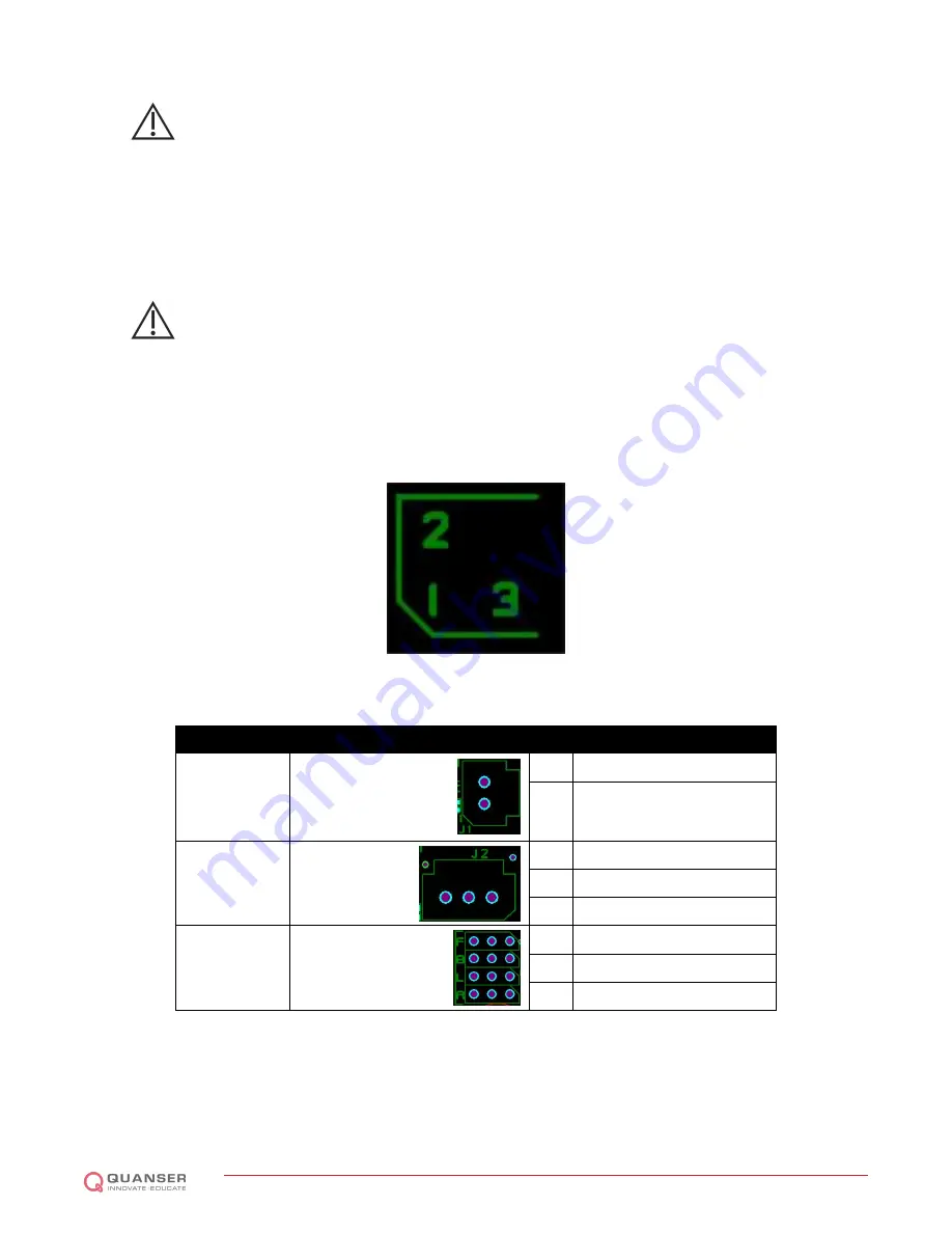
The QBall 2 DAQ provides several I/O channels for interfacing additional sensors. Figure 6.2 shows the QBall 2
DAQ and its interfaces. Figure 6.5 shows the layout of the QBall 2 DAQ header pins and Table 6.4, Table 6.5 and
Table 6.6 list the various I/O pins found on the QBall 2 DAQ.
Figure 6.5: Pin mapping for the DAQ headers
I/O
Header
Pin
Signal
Power input
J1
1
V
in
2
GND
Sonar input
J2
1
5V
2
sonar height measurement
3
GND
Motor outputs
ESC F/B/L/R
1
PWM motor output
2
Not connected
3
GND
Table 6.4: QBall 2 DAQ pin list: J1, J2, ESC F/B/L/R
QBALL 2 - User Manual
DRAFT - April 6, 2015


