background image

Chapter 1 


QDSP-2050 User’s Manual 

Mechanical Figures 


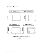
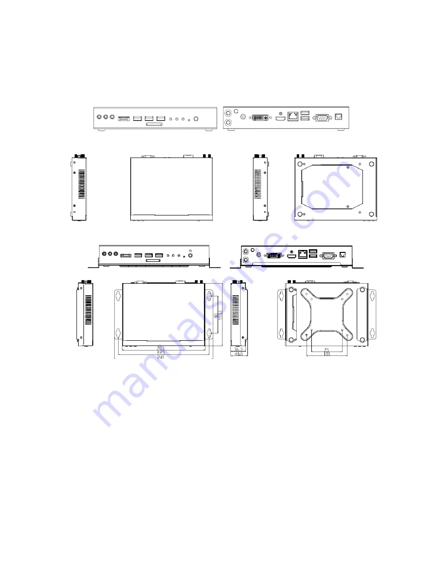
Dimension: 203 x 153.1 x 36.3 mm (W x H x D)   


Figure 3 Mechanical Figures

Summary of Contents for QDSP-2050

Page 1: ...QDSP 2050 User s Manual QDSP 2050 Small PC with Intel Calpella Platform User s Guide...

Page 2: ...property of their respective owners All rights reserved This user s guide contains information proprietary to Quanmax Customers may reprint and use this user s guide in other publications Customers m...

Page 3: ...8 Regulatory Compliance Statements 8 Warranty Policy 9 Maintaining Your Computer 10 Chapter 1 Introduction 13 Overview 13 System tour 15 Mechanical Dimensions 19 Chapter 2 Getting Started 20 Setting...

Page 4: ...rd 25 Figure 13 SO DIMM Installation 1 26 Figure 14 SO DIMM Installation 2 26 Figure 15 mini PCIe Installation 27 Tables Table 1 QDSP 2050 Product Specifications 14 Table 2 BIOS Main Menu 27 Table 3 A...

Page 5: ...hen installing or removing components Refer to the installation instructions in this user s guide for precautions and procedures If you have any questions please contact with your dealer for Post Sale...

Page 6: ...cable itself Some cables have a connector with locking tabs If you are disconnecting this type of cable press in on the locking tabs before disconnecting the cable As you pull connectors apart keep th...

Page 7: ...ard Hold a board by its edges or by its metal mounting bracket Do not handle or store system boards near strong electrostatic electromagnetic magnetic or radioactive fields Instructions for Lithium Ba...

Page 8: ...ervice immediately Refer to Warranty Policy for the return procedure Regulatory Compliance Statements This section provides the FCC compliance statement for Class A devices FCC Compliance Statement Th...

Page 9: ...rranty is void if the product has been subjected to alteration neglect misuse or abuse if any repairs have been attempted by anyone other than your manufacturer or its authorized agent or if the failu...

Page 10: ...ata of any kind or for any direct indirect incidental or consequential damages in connection with or arising out of the performance or use of any product furnished hereunder Our liability shall in no...

Page 11: ...ause sealed components with internal pressure such as electrolytic capacitors to fail or perform at reduced efficiency Power Protection The greatest threats to a system s supply of power are power los...

Page 12: ...tery can provide power to the system for a limited amount of time depending on the UPS system UPS systems range in price from a few hundred dollars to several thousand dollars with the more expensive...

Page 13: ...orm with intel HM55 chipset it provides the powerful computing and graphic performance with the optimal energy efficiency Checklist QDSP 2050 Power Adapter Power Cord Driver CD Quick installation Guid...

Page 14: ...utton 1x 3 in 1 Card Reader SD MMC MS Rear IO 1x DC JACK for power input 1x DVI I for DVI D or VGA output 1x HDMI V1 3 compatible 1x RJ 45 GbE port 2x USB 2 0 1x COM Port support RS 232 422 485 Offer...

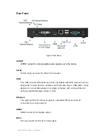
Page 15: ...less than three seconds Power LED Green The power LED will light when the PC is power on HDD LED Red The hard disk LED blinks when data is being written into or read from the HDD WiFi LED Blue When t...

Page 16: ...out signal to amplified speakers or headphones MIC IN The microphone jack is designed to connect the microphone used for video conferencing voice narrations or simple audio recordings Line IN The Lin...

Page 17: ...port is compatible with USB devices such as keyboards mouse devices cameras and hard disk drives USB allows many devices to run simultaneously on a single computer with some peripheral acting as addit...

Page 18: ...th this jack Power supplied through this jack supplies power to the PC To prevent damage to the PC always use the supplied power adapter WiFi External Antenna Spared hole on the casing for connecting...

Page 19: ...Chapter 1 QDSP 2050 User s Manual Mechanical Figures Dimension 203 x 153 1 x 36 3 mm W x H x D Figure 3 Mechanical Figures...

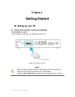
Page 20: ...ard Connecting the monitor Connect the DVI cable from your display to the DVI port Figure 4 Connect the DVI cable NOTE When the system reboots without connecting the DVI there might be no image on scr...

Page 21: ...mputer Figure 5 Connecting USB mouse keyboard NOTE Using a third party USB mouse or keyboard may require software drivers Check the manufacturer s website for the latest software drivers Connecting to...

Page 22: ...Connect the power adapter cable to the DC jack DC IN of the QDSP 2050 2 Connect the power cable to the power adapter 3 Connect the power cable to a power outlet 4 Press the power switch on the front...

Page 23: ...out the VESA mounting kit form your package and facing it onto the bottom of QDSP 2050 then tightening the screws on your QDSP 2050 as figures shown below Figure 8 VESA Mount Assembly 2 Following fig...

Page 24: ...place the QDSP 2050 on the VESA mounting kit and then tightening the screws from the holes on both sides of the VESA bracket make sure the computer is fitting well on the bracket Figure 10 VESA mounti...

Page 25: ...mini PCIe Firstly Opening the cover by loosening the two screws on the bottom of QDSP 2050 as shown below Figure 11 Opening the Cover on the Bottom Then you may able to change the DDR SO DIMM and or...

Page 26: ...ree angle into the socket Figure 13 SO DIMM Installation 1 Align the SO DIMM Memory Module with the onboard socket 4 Fully insert the module into the socket until a click is heard 5 Press down on the...

Page 27: ...QDSP 2050 User s Manual Changing mini PCIe 1 Place your mini PCIe module toward the mini PCIe socket Figure 15 mini PCIe Installation 2 Tightening the screw on the hole of the mini PCIe module as sho...

Page 28: ...please contact with us AMI s ROM BIOS provides a built in Setup program which allows the user to modify the basic system configuration and hardware parameters The modified data will be stored in a bat...

Page 29: ...LITY M a i n A d v a n c e d B o o t S e c u r i t y S a v e E x i t BIOS Information Project version 0 05 Build date 10 22 2010 CPU Information Intel Core i7 CPU M 620 2 67GHz Microcode Revision 9 Pr...

Page 30: ...r management Configuration SATA Configuration USB Configuration H M Monitor Super IO Configuration Select Screen Select Item Enter Select Change Opt F1 General Help F2 Previous values F3 Optimized Def...

Page 31: ...ry Options 128MB 256MB Maximum Table 5 Advanced Power Management Configuration BIOS SETUP UTILITY M a i n A d v a n c e d B o o t S e c u r i t y S a v e E x i t ACPI Sleep State S3 Suspenf to R Resto...

Page 32: ...d SATA Configuration BIOS SETUP UTILITY M a i n A d v a n c e d B o o t S e c u r i t y S a v e E x i t SATA Configuration SATA Port1 WDC WD800BEVS 80 0GB SATA Port2 Not Present SATA Mode IDE Mode Sel...

Page 33: ...2 Previous values F3 Optimized Defaults F4 Save ESC Exit V02 00 1201 Copyright 2009 American Megatrends Inc Legacy USB Support Options Enabled Disabled Auto Table 8 Advanced H W Configuration BIOS SET...

Page 34: ...Configuration Serial Port 1 BIOS SETUP UTILITY M a i n A d v a n c e d B o o t S e c u r i t y S a v e E x i t Serial Port 1 Configuration Serial Port Enabled Device Settings IO 3F8h IRQ 4 Change Sett...

Page 35: ...to Serial port 1 Type RS232 Serial Port 1 Power Normal Enable or Disable Serial Port COM Select Screen Select Item Enter Select Change Opt F1 General Help F2 Previous values F3 Optimized Defaults F4 S...

Page 36: ...able or Disables Quiet Boot Option Select Screen Select Item Enter Select Change Opt F1 General Help F2 Previous values F3 Optimized Defaults F4 Save ESC Exit V02 00 1201 Copyright 2009 American Megat...

Page 37: ...ect Item Enter Select Change Opt F1 General Help F2 Previous values F3 Optimized Defaults F4 Save ESC Exit V02 00 1201 Copyright 2009 American Megatrends Inc Save Exit Menu Table 14 Save Exit Menu BIO...

Page 38: ...save the changes that you made to the Setup program If you made changes to fields other than system date system time and password the BIOS asks for a confirmation before exiting Discard Changes Discar...

Page 39: ...lled you will need to install an operating system and the necessary drivers to operate it After you have finished assembling your system and connected the appropriate power source power it up using th...

Reviews: