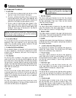
Quadra-Fire CB1200-C Owner'S Manual Download Page 15

15

7027-802K

10/21

HW

RST

Figure 15.1

Figure 15.3

 - Full battery icon

Figure 15.4

 - Low battery icon

Figure 15.2

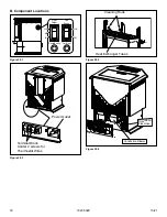
CONNECT THERMOSTAT WIRES TO APPLIANCE: 

There  is  a  4  screw  terminal  block  located  on  the  back 

lower  left  corner  of  the  stove  directly  above  the  power 

cord  inlet.  The  center  2  screws  are  for  the  thermostat 

wires 

(Figure 15.5)

.

Power Outlet

Terminal Block.

Center 2 screws for

Thermostat Wires

Figure 15.5

SOFTWARE RESET:

Software  reset  is  used  to  erase ALL  temperature  events, 

and to return all user-adjustable software settings back to 

their original factory default settings.
To Perform a Software Rest:
1.  Verify the thermostat’s keypad is not locked.
2.  Move TEMPERATURE switch to OFF.
3.  Press and hold the UP, DOWN, and NEXT buttons all 

at the same time for at least 5 seconds. When the LCD 

display screen will become fully populated let go of all 

buttons at that point the screen will return to normal.

The clock will have to be changed to match the current day 

and time.

S. Thermostat Battery Replacement

This thermostat is powered by two “AA” Alkaline batteries. 

The batteries should be replaced AT LEAST once per year to 

ensure reliable operation or sooner if the LO BATT appears 

on  the  display  screen.  The  batteries  are  located  on  the 

back of the thermostat’s circuit board. The front portion of 

the thermostat can be removed from the back half by using 

the tabs on the top edge of the thermostat housing (

Figure 

15.2

).

HARDWARE RESET:

The  hardware  reset  button;  labeled  HW  RST,  is  a  small 

round push button that is located in the middle of the circuit 

board, just below the battery holder 

(Figure 15.1)

. Pressing 

this button will:
•  Cause the LCD display screen to become fully populated
•  Thermostat  to  perform  an  internal  system  check  of 

its components

If the thermostat appears to be acting in an erratic manner, 

pressing  the  HW  RST  button  may  remedy  this  behavior. 

The temperature programs are not erased when a hardware 

reset  is  performed,  however  the  clock  will  have  to  be 

changed to match the current day and time.

When installing new batteries, it is recommended using only 

brand  new  “AA”  size  alkaline  batteries.  Please  verify  the 

polarity markings shown in the battery compartment before 

adding  batteries  to  the  compartment.  When  finished,  line 

up the front of the thermostat to the base, and firmly press 

together to securely latch the front and back halves together 

properly.

BATTERY GRAPHIC:

Anytime  time  the  batteries  are  physically  present  in  the 

thermostat, there will be a visual indicator showing the life of 

the battery. This will appear on the display screen (

Figures 

15.3 and Figure 15.4

).

Shock hazard.

•  Do  NOT  remove  grounding  prong 

from plug.

•  Plug  directly  into  properly  grounded  3 

prong receptacle.

•  Route cord away from appliance.

•  Do  NOT  route  cord  under  or  in  front 

of appliance.

CAUTION

Summary of Contents for CB1200-C

Page 1: ...anual please contact your dealer or visit www quadrafire com REMARQUE Pour obtenir une traduction fran aise de ce manuel s il vous pla t contacter votre revendeur ou visitez www quadrafire com Tested...

Page 2: ...trictions and inspection in your area WARNING FOR MOBILE HOMES Do not install appliance in a sleeping room An outside combustion air inlet must be provided The structural integrity of the mobile home...

Page 3: ...e Safety 8 B Non Combustible Materials 8 C Combustible Materials 8 D Fuel Material and Fuel Storage 8 E Before Your First Fire 9 F Filling the Hopper 9 G General Operating Information 10 H Starting Yo...

Page 4: ...earlier However the Warranty coverage shall commence no later than 24 months following the date of Product shipment from HHT regardless of the installation or occupancy date The term Lifetime in the t...

Page 5: ...forced air furnaces or other such causes 6 use of fuels other than those specified in the operation instructions 7 installation or use of components not supplied with the applicable Product or any ot...

Page 6: ...with the requirements of CSA B415 1 Arange of BTU outputs calculated using HHV efficiency and the burn rates from the EPA tests Based on the maximum feed rate per hour multiplied by approximately 860...

Page 7: ...e properly grounded to the frame of the mobile home and use only Listed pellet vent Class L or PL connector pipe Outside Air Kit part 811 0570 or 811 0872 must be installed in a mobile home installati...

Page 8: ...d maintain regularly Conveniently locate a Class A fire extinguisher to contend with small fires In the event of a hopper fire Evacuate the house immediately Notify fire department B Non Combustible M...

Page 9: ...hat would hinder routine cleaning and maintenance Size Pellets are either 1 4 inch or 5 16 inch 6 8mm in diameter Length should be no more that 1 1 2 inches 38mm Pellet lengths can vary from lot to lo...

Page 10: ...hermostat is calling for heat 6 Once the appliance has ignited let it burn for approximately 15 minutes then set the thermostat to the desired room temperature Adjust the heat output control switch to...

Page 11: ...ld see a fire shortly If not follow Starting Your First Fire on page 10 L Restarting the Appliance Restart Process 1 When the unit has run out of fuel add pellet fuel to the hopper 2 Dump the ashes an...

Page 12: ...RCOAL LIGHTER FLUID OR SIMILAR LIQUIDS TO START OR FRESHEN UP A FIRE IN THIS APPLIANCE DO NOT BURN GARBAGE OR FLAMMABLE FLUIDS SUCH AS GASOLINE NAPHTHA OR ENGINE OIL DO NOT USE CHEMICALS OR FLUIDS TO...

Page 13: ...ries from the desired set point temperature Use the UP DOWN buttons to change the number value between 1 and 9 Generally your system should cycle on about 3 to 6 times per hour A smaller differential...

Page 14: ...eatures need to be completed in a timely manner as the thermostat will time out after 10 seconds NOTE The word COPY will not appear on the display for Monday but will display each day afterwards for a...

Page 15: ...of the thermostat can be removed from the back half by using the tabs on the top edge of the thermostat housing Figure 15 2 HARDWARE RESET The hardware reset button labeled HW RST is a small round pu...

Page 16: ...enance and Service on page 17 What is the metal object with the bend in it that came inside the plastic bag It is a clean out tool used to help clean the fire pot and remove any jams in the rare event...

Page 17: ...l types OR X Top Vent Adapter More frequently depending on the fuel type or ash build up OR X Venting System More frequently depending on the fuel type OR X Follow the detailed instructions found in t...

Page 18: ...move ash with an ash vacuum or whisk broom and small dust pan d This ash is deposited in the same ash pan as the fire pot debris The ash pan should be emptied every time you clean the firebox Remember...

Page 19: ...appliance is allowed to cool has been unplugged and the exhaust blower is off b Empty the hopper of any remaining pellets c Vacuum the hopper and feed tube 6 Cleaning Heat Exchanger Chambers Drop Tub...

Page 20: ...epending on ash build up By Qualified Service Technician Homeowner Be sure the appliance is allowed to cool has been unplugged and the exhaust blower is off The products of combustion will contain sma...

Page 21: ...rom the firebox and vacuum thoroughly c Paint all exposed steel including cast iron Use the Touch Up paint supplied with the appliance or Purchase paint from your local dealer Must use a high temperat...

Page 22: ...Homeowner Poor quality pellet fuel or lack of maintenance can create conditions that make the fire pot fill quickly with ashes and clinkers This condition makes the appliance susceptible to overfilli...

Page 23: ...n fire pot Fire pot clean out plate not closed Fire pot is dirty The ignition hole between the igniter bracket and fire pot is blocked Igniter not working Control box defective Check that fire pot cle...

Page 24: ...t or does not shut off Blower not plugged in Blower is clogged with ash Blower is defective Control box is defective Check that blower is plugged into wire harness Clean exhaust system Replace blower...

Page 25: ...to housing c Re connect wiring use jumper wire if necessary Re connect power supply Remove 2 Screws Remove 4 Screws Outside Air Flex Hose Convection Blower Figure 25 2 5 5 Service Parts Replacement 2...

Page 26: ...and remove the ash drawer 2 Follow instructions to remove the ash pan found on page 18 Cleaning Ash Pan Remove the access plate directly above it by removing the 2 screws just below the ash catcher 3...

Page 27: ...frame and slightly bend up and out of the way d Slide glass out the side and slide new glass in e Re install the side glass frame and tighten the top and bottom frames f Re install the door latch if...

Page 28: ...Check the wall receptacle for 120 volt 60 Hz standard current Make sure the outlet is grounded and has the correct polarity A good surge protector is recommended 13 Red Call Light The red call light i...

Page 29: ...xchanger system is dirty or plugged or if the firebox door is open 21 Wiring Harness See Figure 29 1 below 16 Thermostat The appliance is designed to run on a 12 volt AC thermostat The heat anticipato...

Page 30: ...Tubes Figure 30 2 Power Outlet Terminal Block Center 2 screws for Thermostat Wires Figure 30 3 Figure 30 1 Heat Output Fan Speed Reset Button Call Light HIGH HIGH MED LOW LOW Outside Air Flex Hose Con...

Page 31: ...31 7027 802K 10 21 C Service and Maintenance Log Date of Service Performed By Description of Service...

Page 32: ...32 7027 802K 10 21 Date of Service Performed By Description of Service...

Page 33: ...33 7027 802K 10 21 Date of Service Performed By Description of Service...

Page 34: ...March 2019 Ending Manufacturing Date Active Classic Bay Freestanding Pellet Stove Part number list on following page 04 21 1 6 2 7 8 9 3 4 5 10 11 12 13 14 15 16 17 17 22 18 19 20 21 23 24 25 26 27 3...

Page 35: ...2 Pkg of 12 220 0490 12 Y Hopper Lid Magnetic Switch SRV7000 375 Y 2 Baffle Assembly Left 510 5350 3 Baffle Assembly Right 510 5360 4 Hinge Plate 812 4030 Hinge Door Male SRV450 2810 Screw Pan Head Ph...

Page 36: ...Loop Igniter Pkg of 1 SRV7000 462 Y Pkg of 10 SRV7000 462 10 Y Wing Thumb Screw 8 32 X 1 2 Pkg of 24 7000 223 24 Y 11 2 Combustion Plenum Trap Door 812 4100 12 Thermocouple Cover Qty 1 812 1322 Y Pkg...

Page 37: ...Y 22 Snap Disc Convection Blower 1 SRV230 0060 Y 23 Convection Blower 130 60 CFM 812 3370 Y Nut Keps Lock 8 32 Pkg of 40 226 0060 40 Y Screw Pan Head Philips 8 32 X 3 4 Pkg of 24 229 1100 24 Y 24 Snap...

Page 38: ...Assembly SRV229 0920 36 Control Board 3 Speed SRV7000 704 Y Fuse 8 Amp Control Box Pkg of 10 812 3780 10 Y 37 Cover Control Box 410 6321 38 Feed Adjustment Plate 812 4170 39 Cover Feed Motor SRV7027 0...

Page 39: ...nt 812 3570 Damper 3 Inch Tall Vertical Installs Only PEL DAMP3 Y Damper 4 Inch Tall Vertical Installs Only PEL DAMP4 Heat Exchange Repair Kit 812 4970 Log Set 811 0592 Outside Air Kit Floor 811 0570...

Page 40: ...maintenance instructions included Read understand and follow these instructions for safe installation and operation Leave this manual with party responsible for use and operation of this appliance We...

Reviews: