background image

R

October 24, 2011

Page  17

Castile & Santa Fe CE Pellet Stove 

7068-112B

5

Getting Started

Installer’s Guide

A.  Design, Installation & Location Considerations

WARNING! Risk of Fire


Damaged parts could impair safe 

operation. Do NOT install damaged, incomplete or substitute 

components. 

1. Appliance Location

NOTICE: 

Check building codes prior to installation.

•  Installation  MUST  comply  with  all  local  building  codes 

and regulations including those referring to national and 

European standards.

•  Consult  insurance  carrier,  local  building  inspector,  fire 

officials or authorities having jurisdiction over restrictions, 

installation inspection and permits.

It is a good idea to plan your installation on paper, using exact 

measurements  for clearances and floor protection, before 

actually beginning the installation.  Location of the appliance 

and chimney will affect performance.
Consideration must be given to:
•  Safety, convenience, traffic flow
•  Placement of the chimney and chimney connector and to 

minimize the use of chimney offsets.  

•  Place the appliance where there will be a clear passage 

for a Listed chimney through the ceiling and roof (verti

-

cal) or through exterior wall (horizontal).  

•  Installing the required outside air kit will affect the loca

-

tion of the vent termination.

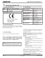
Marginal Location:

•  Below peak

Location NOT recommended:

•  Not the highest point of the roof

•  Wind loading possible

Multi-level Roofs

Windward 

Leeward

Recommended:

Outside Air Intake

on windward side

NOT recommended:

Outside Air Intake

on leeward side

Recommended Location:

•  Above peak

Recommended:

•  Insulated exterior chase 

in cooler climates

Recommended Location:

•  Above peak

•  Inside heated space

Location NOT recommended:

•  Too close to tree

•  Below adjacent structure

•  Lower roof line

•  Avoid outside wall

Marginal Location:

•  Wind loading possible

Figure 18.1

Since pellet exhaust can contain ash, soot or sparks, you 

must consider the location of:
•  Windows

•  Air Intakes

•  Air Conditioner

•  Overhang, soffits, porch roofs, adjacent walls 

•  Landscaping, vegetation

•  Horizontal or vertical vent termination
When locating vent and venting termination, the ideal lo

-

cation is to vent above roof line when possible.  This mini

-

mizes the affects of wind loading.

2. Floor Support

The  supporting  floor  under  the  appliance  must  be  able 

to  handle  the  weight  of  the  appliance,  fuel  load  and  the 

weight of the chimney.
Ensure that your floor will suport these weights prior to in

-

stallation.   Add  sufficient  additional  support  to  meet  this 

weight requirment prior to installation.  The weight of this 

appliance is 109 kg and with a full hopper of fuel weighing 

18 kg, the total for the appliance and fuel is 137 kg.

Summary of Contents for CASTILE-CE-MBK

Page 1: ...esponsible for use and operation Read understand and follow these instruc tions for safe installa tion and operation DO NOT DISCARD WARNING Hot glass will cause burns Do not touch glass until it is co...

Page 2: ...voeding 470 W Rated Voltage Tension nominale Nominale spanning 230 V 50 Hz Safety clearance distance back Distance de d gagement de s curit retour Veiligheidsafstand afstand terug 50 mm Safety clearan...

Page 3: ...lame Height Adjustment Feed Rate 10 J Ignition Cycles 10 K Clear Space 10 Section 3 Maintaining Servicing Appliance A Proper Shutdown Procedures 11 B Quick Reference Maintenance Chart 11 C General Mai...

Page 4: ...Page 4 October 24 2011 Castile Santa Fe CE Pellet Stove R 7068 112B...

Page 5: ...R October 24 2011 Page 5 Castile Santa Fe CE Pellet Stove 7068 112B...

Page 6: ...Overfire Install any component not approved by Hearth Home Technologies Install parts or components not Listed or approved Improper installation adjustment alteration service or maintenance can cause...

Page 7: ...E children in same room as appliance Alert children and adults to hazards of high temperatures High temperatures may ignite clothing or other flammable materials Keep clothing furniture draperies and...

Page 8: ...ppliance robbing heat from your home Damp pellet fuel can clog the feed system Size Pellets are either 6 or 8mm in diameter Length should be no more that 38mm Pellet lengths can vary from lot to lot f...

Page 9: ...our appliance will automatically light and deliver heat When the room is up to temperature and the thermostat is satisfied the red call light will go off and the appliance will shut down 2 Heat Output...

Page 10: ...minutes This blower transfers heat from your appliance into the room and will continue to run after the thermostat has stopped calling for heat until the appliance has cooled down 3 Occasionally the a...

Page 11: ...build up OR X Ash Removal from Firebox Every 5 bags or more frequently depending on the fuel type or ash build up OR X Beneath Heat Exchanger Every 1 ton of fuel OR X Blower Combustion Exhaust More f...

Page 12: ...ust blower and vent system b Plug in your appliance if unplugged and turn the thermostat on and immediatley shut it off to start the exhaust blower on its cycle time It will pull fly ash out the exhau...

Page 13: ...d close cast hinge face 10 Cleaning the Hopper Frequency Monthly or after burning 50 bags of fuel By Homeowner After burning approximately 1 ton of fuel you will need to clean the hopper to prevent sa...

Page 14: ...e Technician Task Contact your local dealer 14 Cleaning Convection Blower Requires No Lubrication Frequency Yearly or every 25 bags or more fre quently depending on operating environ ment By Qualified...

Page 15: ...and possible hopper fires Poor quality pellet fuel or lack of maintenance can create conditions that make the firepot fill quickly with ashes and clinkers This condition makes the appliance susceptib...

Page 16: ...oot 3 Excessive build up of ash See solution 4 The lower burn settings will produce more ash the higher burn settings produce less The more it burns on low the more frequent cleaning of the glass is r...

Page 17: ...affect the loca tion of the vent termination Marginal Location Below peak Location NOT recommended Not the highest point of the roof Wind loading possible Multi level Roofs Windward Leeward Recommende...

Page 18: ...dealer any parts damaged in shipment All labels have been removed from the glass door Plated surfaces have been wiped clean with a soft cloth if applicable Read all the instructions before starting th...

Page 19: ...ew Figure 20 1 Top View Figure 20 3 Side View Figure 20 4 Side View with Top Vent Adapter 658mm 324mm 540mm 729mm 426mm 715mm 653mm 95mm 64mm 73mm 683mm 609mm 626mm 305mm 609mm 725mm 405mm 582mm 431mm...

Page 20: ...Appliance 50 H Side Wall to Flue Pipe 76 Alcove Installation Millimeters Minimum Alcove Height 1092 Minimum Alcove Side Wall 152 Minimum Alcove Width 965 Maximum Alcove Depth 914 Dimension to Corner M...

Page 21: ...tion Figure 22 3 Figure 22 4 Must extend 51mm beyond each side of pipe shaded area C Hearth Pad Requirements If the current flooring is made from wood provide adequate surface protection according to...

Page 22: ...service shall be the same as minimum clearance to vinyl soffits Clearance of a termination cap above electrical service will be 305mm minimum Location of the vent termination must not obstruct or inte...

Page 23: ...erformance of the chimney system caused by Inadequate draft due to environmental conditions Downdrafts Tight sealing construction of the structure Mechanical exhausting devices D Draft To minimize the...

Page 24: ...with at least 3 screws through each joint 5 DO NOT INSTALL A FLUE DAMPER IN THE EXHAUST VENTING SYSTEM OF THIS UNIT 6 DO NOT CONNECT THIS UNIT TO A CHIMNEY FLUE SERVING ANOTHER APPLIANCE NOTE All pipe...

Page 25: ...foot Hearth Home Technologies recommends any installation requiring more than two 90 elbows or more than 4 5m of venting to use 102mm vent NOTICE These are guidelines for successful venting of your pe...

Page 26: ...and are FOR DESIGN PURPOSES ONLY Illustrations diagrams are not drawn to scale Actual installation may vary due to individual design preference A Alcove Figure 27 1 All minimums listed are to a combus...

Page 27: ...actures listed air clearances to combustibles and installation instructions for all reduced air clearances installations The stove must be connected to a flue pipe conforming to current standards UNI...

Page 28: ...FE Non combustible Hearth Pad Airtight Cleanout Door Cleanout cover Sheathing 76mm Minimum 25mm Clearance Flashing Fireclay flue Liner with Airspace Concrete Cap 25mm Clearance with Firestop 152mm Mi...

Page 29: ...e Horizontal Termination Cap 51mm Minimum 152mm Minimum From Glass NOTICE Please note that while the minimum clearance for the termination cap is 152mm there is the possibility of soot build up around...

Page 30: ...e saw to cut opening in wall Cut a 64 to 76mm open ing on inside wall and a 76 to 89mm opening on outside of house 2 Remove cover plate and then install the collar assembly 3 Use hose clamp to secure...

Page 31: ...tional programmable thermo stat or remote control It is equipped with an adjustable heat anticipator The current rating is 05 amps The anticipator needs to be adjusted to the lowest setting available...

Page 32: ...instruc tions included Leave this manual with party responsible for use and operation Read understand and follow these instruc tions for safe installa tion and operation DO NOT DISCARD Date purchased...

Reviews: