background image

4100-I  ACT Wood Insert

Page 0

 April 19, 2010

R

250-7201F

Service Parts

2/10

R

7025-029

Wood Insert Appliance

4100-I ACT

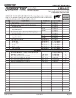
IMPORTANT: THIS IS DATED INFORMATION. When requesting service or replacement 

parts for your appliance please provide model number and serial number. All parts listed 
in this manual may be ordered from an authorized dealer.

Stocked

at Depot

ITEM

DESCRIPTION

COMMENTS

PART NUMBER

1

Ceramic Fiber Blanket, 1/2“ Thick

82-90

Y

2

Baf

fl e, Fiberboard

82-520

Y

Manifold Tube Set

Set of 4

82-50

Y

Manifold Clip/Screws 

82-0661

Y

4

Top, Cast

45-000

5

Panel, Wire Access

45-0900

6

Blower Control Box w/Switch (Included wire harness)

Post 145128

SRV7000-194

Y

7

Wire Harness Only

Pre 145127

45-1420

8

Blower Replacement

Post 1451097

82-491

9

Blower Mount Clamp

Qty: 2 Req.

45-0400

10

Base, Blower Mount

Post 1451097

45-020

11

Blower Housing Cast

45-0590

12

Ashcatcher, Cast

45-010

1

Snap Disc, 110-20 degrees

SRV20-1220

Y

14

knob, Air Control

2284

Y

15

Outside Air Cover Plate

45-0290

16

Outer Top

45-0260

17

Flue Tab

48-0010

Component Pack (Includes Owners Manual, Touch-Up 

Paint, Warranty Card, 2 Screws, Permanent Label “If 

Fireplace Altered”)

45-510

Paint Touch-Up

7000-04

Wire Extension, Blower, 12”

45-0920

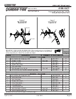
ACCESSORIES

Adjustable Hearth Support,   9” d x 45” w,  2”-10” High

841-0990

Adjustable Hearth Support, 12” d x 50” w,  2”-10” High

ADJSPT-12

Trim Front

481-0160

Trim Side

481-0090

Panel & Trim, Small - 44.5 W x 0.5 H

Gold

SP-BB044-GD

Bracket, -L-, Trim

Qty: 2 Req.

82-0840

Component Pack

45-5540

Logo, Quadra-Fire

Gold

200-180

Trim Set Only

Gold

7000-007

Panel & Trim, Small - 44.5 W x 0.5 H

Nickel

SP-BB044-NL

Bracket, -L-, Trim

Qty: 2 Req.

82-0840

Component Pack

45-5550

Logo, Quadra-Fire

Nickel

200-240

Additional service part numbers appear on following page.

Beginning Manufacturing Date: July 2002 

Ending Manufacturing Date: Active

Summary of Contents for 4100I-GD-B

Page 1: ...T Advanced Combustion Technology ACT O T L Tested and Listed by Portland Oregon USA OMNI Test Laboratories Inc C US 250 7201F R Installation and service of this appliance should be performed by qualif...

Page 2: ...INSERT Serial No Num ro De S rie Report 061 S 40 2 Made in U S A U S ENVIRONMENTAL PROTECTION AGENCY Certified to comply with July 1990 particulate emission standards 2010 2011 2012 Jan Feb Mar Apr M...

Page 3: ...ents 11 Altering the Fireplace 11 Ovalizing Round Stainless Steel Liners 12 Chimney Height Rise Run 12 Air Clearances 12 Chimney Termination 2 10 3 Rule 13 Installation Considerations Mobile Home Inst...

Page 4: ...e An OutsideAir Kit comes standard on the appliance and must be installed in a mobile home installation Mobile Home Approved NOTE Hearth Home Technologies grants no warranty implied or stated for the...

Page 5: ...iently located Class A fire extinguisher to contend with small fires resulting from burning embers 3 A practiced evacuation plan consisting of at least two escape routes 4 A plan to deal with a chimne...

Page 6: ...FRONT VIEW NOTE Flue Collar size is 6 inch 152mm diameter ID 20 7 8 5 0mm 0 o 10 7 8 276mm 21 5 8 549mm 7 7 8 200mm 16 1 4 41 mm C L 24 610mm 0 16 767mm 12 1 8 08mm 9 5 16 1 5mm 45 4 1162mm A B 0 7 8...

Page 7: ...of a material s resisteance to heat transfer R value is convenient when more than one material is used since you can add the R values together whereas you can not do this for k value The HIGHER the R...

Page 8: ...to the rear of the smoke shelf Minimum 1 2 25mm Air Space Maximum 4 102mm Air Space Airtight Clean Out Door Minimum 5 8 16mm Fireclay Flue Liner Non Water Soluble Refractory Mortar 4 102mm Masonry or...

Page 9: ...with Insert Listing Follow Manufacturer s Instructions for Maximum Liner Extension Above Chimney Maximum 30 Degrees Offset in Chimney Combustible Floor Masonry Chimney Cont d Figure 9 1 NOTE In Canad...

Page 10: ...op The air flow of the factory built zero clearance fireplace system must not be altered The flue liner top support attachment must not reduce the air flow for the existing air cooled chimney system N...

Page 11: ...creen Curtain Doors The following parts may be removed Fire Risk When lining air cooled factory built chimneys Run chimney liner approved to UL 1777 Type HT requirements 2100 degrees F Re install orig...

Page 12: ...y vary somewhat for individual installations This product was designed for and tested on a 6 inch 152mm chimney 14 to 16 feet 4 27 4 87m high in cludes appliance height measured from the base of the a...

Page 13: ...roof within 10 feet 305cm Must be located away from trees or other structures These are safety requirements and are not meant to assure proper flue draft NOTE Chimney performance may vary Trees buildi...

Page 14: ...ay be required 3 Appliance must be grounded with 8 solid copper grounding wire or equivalent and terminated at each end with N E C approved grounding device 4 The factory built fireplace must meet UM...

Page 15: ...s or chimneys Fumes or odor may result Fire Risk Asphyxiation Risk Asphyxiation Risk Length of outside air supply duct shall NOT exceed the length of the vertical height of the exhaust flue Fire will...

Page 16: ...may hang up on uneven material when sliding the insert into place Figure 16 1 Adjusting The Leveling Bolts It is best to use a 1 2 inch 12 7mm socket wrench with an extended handle for ease in adjust...

Page 17: ...ght edge 5 The double sided tape that holds front and side trims to scissors has a powerful bonding adhesive Adjust ments are extremely difficult once trim has adhered to tape Do a dry run first witho...

Page 18: ...andard Size 30 h x 40 w Panel And Gold Trim Set 1 Repeat Steps 1 3 above 2 To assemble the trim attach the 2 side trim pieces to the top trim at each corner using the L bracket included in fasteners p...

Page 19: ...Location Black Red White Snap Disc Blower Control Box with Switch Cooling Fan Black Operating the Blower Control Box with Snap Disc 1 The blower will turn on off automatically when set to AUTO 2 When...

Page 20: ...ft not evaporating the moisture out of wet unseasoned wood resulting in wasted heat Do not over fire Over firing may ignite creosote or will damage the stove and chimney To prevent over firing your st...

Page 21: ...Here is one method that works well 1 Place several wads of crushed paper on the firebox floor Heating flue with slightly crumpled newspaper before adding kindling keeps smoke to a minimum 2 Place seve...

Page 22: ...r longer for very large pieces close the Start Up Air Control bottom rod by pulling it out HIGH Leave the Primary Air Control fully open immediately under the ashcatcher It is especially important to...

Page 23: ...ear the top of the glass door This preheated air supplies the necessary fresh oxygen to mix with the unburned gases helping to create second third and fourth combustions This air is regulated by the P...

Page 24: ...n with each other in the front Ceramic Blanket Back of Firebox Baffle Board Figure 24 1 Correct Baffle Ceramic Blanket Placement Firebox damage due to improper baffle place ment is not covered by warr...

Page 25: ...appliance Inspection Inspect the system at the appliance connection and at the chimney top Cooler surfaces tend to build creosote deposits quicker so it is important to check the chimney from the top...

Page 26: ...raft and chimney fires Always burn dry wood to help prevent cap blockage and creosote build up Keeping the door and glass gasket in good shape will maintain good burn times on a low burn setting Check...

Page 27: ...NOTE Soak the bolts with penetrating oil for at least 15 minutes before trying to remove them Figure 27 1 4 To remove manifold tubes slide the tube to one side until one end is out of its hole Then w...

Page 28: ...frame and or side frames 4 Lay new glass with fiberglass tape around it into door frame and or side frames 5 Place glass retainers over the fiberglass tape on the edges of the glass and re install scr...

Page 29: ...lowing page See detailed view on following pages 4 5 Brick 6 7 8 9 10 11 12 14 15 16 17 13 1 2 3 Door Assembly Door Handle Assembly Version 1 Door Handle Assembly Version 2 830 0390 July 2002 April 20...

Page 30: ...ost 1451097 4 5 0 20 11 Blower Housing Cast 4 5 0590 12 Ashcatcher Cast 4 5 0 10 1 Snap Disc 110 20 degrees SRV2 0 1220 Y 14 knob Air Control 2284 Y 15 Outside Air Cover Plate 4 5 0290 16 Outer Top 4...

Page 31: ...eperately 8 1 2010 Component Pack 4 5 55 0 Logo Quadra Fire Gold 200 180 Nickel 200 240 Trim Cast Set 5 pieces Matte Black 811 09 0 Footer Left Matte Black 414 7090MBk Footer Right Matte Black 414 710...

Page 32: ...k Set Complete Assembly Pkg of 20 8 2 500 Y 1 Brick w Hole 9 x 4 5 x 1 25 Pkg of 2 SRV4 5 0800 Y 2 Brick 2 Angle Cut 9 x 4 x 1 25 Qty 2 Req 8 2 0552 Y Brick 4 5 x x 1 25 Qty 1 Req 8 2 055 Y 4 Brick 4...

Page 33: ...ulder 5 16 x 1 4 20 Pkg of 20 22 0170 20 Y Latch Box Assembly must be ordered separately 4 5 5270 Y vERSION 2 Post 1452200 Door Handle Latch Replacement kit SRV4 5 5510 Y 6 Hook Door Latch 4 5 1190 Y...

Page 34: ...ge Pin Rivet M6 x 5 Button Head Gold 72171 Y Nickel 4 1590 Y 2 Trim Ring Front Gold 4 5 0570 Nickel 4 5 0990 Trim Ring Side Gold 4 5 0580 Nickel 4 5 1000 4 Door Frame Cast 4 5 0050 5 Glass Assembly Si...

Page 35: ...Page 35 April 19 2010 4100 I ACT Wood Insert 250 7201F R Date of Service Performed By Description of Service Service And Maintenance Log...

Page 36: ...4100 I ACT Wood Insert Page 36 April 19 2010 R 250 7201F Date of Service Performed By Description of Service Service And Maintenance Log Cont d...

Page 37: ...Page 37 April 19 2010 4100 I ACT Wood Insert 250 7201F R Homeowner s Notes...

Page 38: ...4100 I ACT Wood Insert Page 38 April 19 2010 R 250 7201F...

Page 39: ...Page 39 April 19 2010 4100 I ACT Wood Insert 250 7201F R...

Page 40: ...arty responsible for use and operation Read understand and follow these instructions for safe installation and operation DO NOT DISCARD Date purchased installed Serial Number Location on appliance Dea...

Reviews: