background image


TD-000508 -01      -A

Through-the-Table Mounting


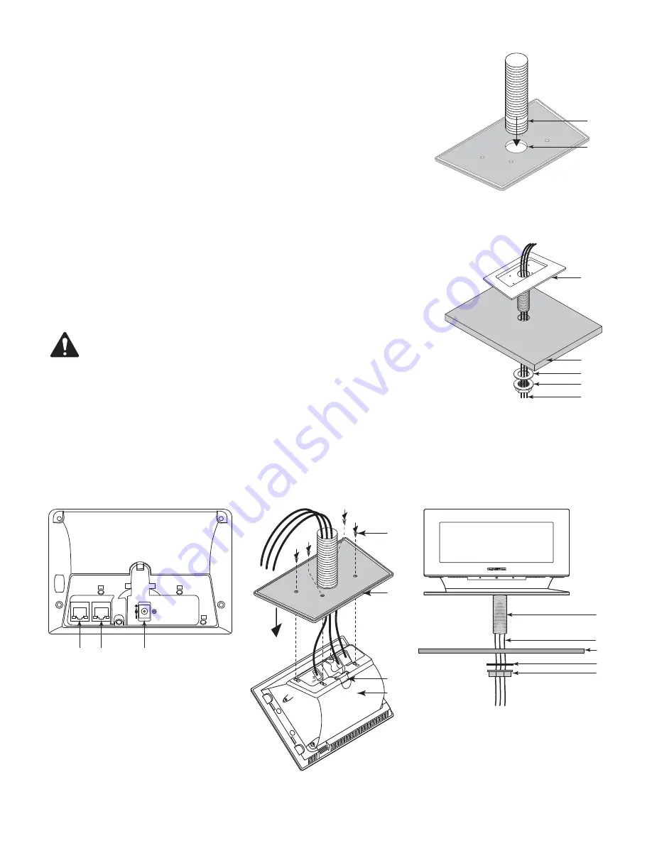
1.  Drill a 33.3 mm (1-5/16 inch) hole through the mounting surface in the spot where you want to 

mount the TSC-7t.

Refer to 

Figure 6

2.  Screw end with fewer threads on Mounting Pipe (1) into the bottom side of the Base (2).

Refer to 

Figure 7

3.  Run the cables (1) through the Nut (2), Washer (3), mounting surface (4), and Mounting Pipe/

Base assembly (5)      

Refer to 

Figure 8

4.  Connect the cables to the proper connectors in the TSC-7t 

a.  LAN A/PoE - required for network. (PoE is optional if you use the 12V DC AUX Power source)

b.  LAN B - optional (for redundant network)

c.  12V DC AUX Power input - optional (required if you are not using PoE)

Refer to 

Figure 9

NOTE: 


If the Cable Cover (3) fell off during disassembly, be sure to replace it before re-

installing the Base (1).

5.  Carefully place the Base (1) onto the TSC-7t body (2). Make sure the cables are not pinched.

6.  Secure the Base to the TSC-7t with the 4 screws (3) removed in “Prepare for Installation (both 

options)”. 

Refer to 

Figure 10

7.  Feed the cables (1) through the mounting surface (2) along with the Mounting Pipe (3).

8.  Move the Washer (4) onto the Mounting Pipe (3), then thread the Nut (5) onto the Mounting Pipe.

9.  Tighten the Nut (5) as needed.

— Figure 6 — 

1

2


— Figure 7 — 

1

2

3

4

5


— Figure 8 — 

LAN A/PoE

LAN B

12V DC

RESET

a

b

c


— Figure 9 — 

2

1

3

3


— Figure 10 — 

1
2

3

4
5


Summary of Contents for TSC-7t

Page 1: ...Hardware Installation Guide TSC 7t Networked Table Mounted 7 Touchscreen Controller TD 000508 01 A TD 000508 01...

Page 2: ...ead these instructions 2 Keep these instructions 3 Heed all warnings 4 Follow all instructions 5 Do not use this apparatus near water 6 Do not submerge the apparatus in water or liquids 7 Do not use a...

Page 3: ...reception which can be determined by turning the equipment off and on the user is encouraged to try to correct the interference by one or more of the following measures Reorient or relocate the receiv...

Page 4: ...n control panels The TSC 7t products are designed to connect to a Q Sys system via Q LAN or to an auxiliary network to which the system Core Processor s is connected The TSC 7t products offer low late...

Page 5: ...cy RJ45 4 12V DC AUX Power input power supply not included 5 Unit Reset Button Touchscreen TSC 7t Packing List 1 Q Sys TSC 7t Touchscreen assembly 1 2 Through the table Mounting Pipe 1 3 Mounting Pipe...

Page 6: ...act 2 5mm 0 2mm Length 9 5mm 0 3mm Installation Configuration Select one of the following 1 Through the Table Mounting Figure 3 a TSC 7t b Mounting Surface table desk c Mounting Pipe 31 6 mm 1 25 in N...

Page 7: ...optional for redundant network c 12V DC AUX Power input optional required if you are not using PoE Refer to Figure 9 NOTE If the Cable Cover 3 fell off during disassembly be sure to replace it before...

Page 8: ...twork c 12V DC AUX Power input optional required if you are not using PoE 4 Carefully route the cables as shown NOTE Some cables may have a protective boot over the RJ45 connector The boots may not fi...

Page 9: ...A Optional Power Source no t included 12V DC AUX Power source not supplied 12V DC 1A 12W Barrel connector Negative contact 5 5mm 0 2mm Positive contact 2 5mm 0 2mm Length 9 5mm 0 3mm Wireless connecti...

Page 10: ...echnical Services Monday Friday 7 AM to 5 PM PST Excludes Holidays Tel 800 772 2834 U S only Tel 1 714 957 7150 Q SYS 24 7 Emergency Support Tel 1 888 252 4836 U S Canada Tel 1 949 791 7722 non U S Q...

Reviews: