


9
Programmable RGB LEDs
The TSC-70-G3 and TSC-101-G3 Touch Screen Controllers include Programmable RGB LEDs grouped into two Lightbars – one
located on each side of the Touch Screen Controller display. Refer to Profile attributes within this document for Programmable RGB LED
locations. Each Lightbar consists of four 24-bit high-brightness RGB (Red Green Blue) LED elements. LED elements may be configured
individually or configured as a set through Q-SYS Designer Software.
Sensors
• All TSC-G3 Series Touch Screen Controller models include an Ambient Light Sensor (ALS). The sensor is located in the upper left
border surrounding the display when the Touch Screen Controller is in its normal landscape orientation. The ALS is always enabled
and produces a numeric value proportional to ambient light intensity. Greater light intensity (higher brightness) produces larger
numeric values. Q-SYS Designer Software tools can be used to configure ALS related features.
• The TSC-70-G3 and TSC-101-G3 Touch Screen Controllers include a Proximity detection sensor. The sensor is located in the upper
left border surrounding the display when the Touch Screen Controller is in its normal landscape orientation. The Proximity sensor is
always enabled and produces a numeric value proportional to detection of nearby objects. Detection of objects closer to the sensor
produces larger numeric values. Sensitivity is geared towards objects within 0.5m in front of the sensor. Q-SYS Designer Software
tools can be used to configure Proximity related features.
NFC (Near Field Communications)
The TSC-G3 Series Touch Screen Controllers include an NFC initiator/reader that is compliant with a number of ISO and IEC standards
and also supports custom protocols. Present support on the TSC-G3 Series Touch Screen Controllers includes scanning for, detecting,
and reading passive targets. The TSC-G3 Series Touch Screen Controllers support type 2 tags (T2T) that are compliant with ISO/IEC
14443A, including MiFare Classic and MiFare Ultralight tags having NTAG21x series ICs. Supported tags are commercially available
in a variety of form factors and storage capacities. Q-SYS Designer Software tools can be configured to display/present tag attributes
and identification (UID) as well as data content type or record type from non-encrypted tags.
To initiate a read event, hold a compliant and supported T2T target over the NFC antenna on the TSC-G3 Series Touch Screen
Controller for approximately 1 to 3 seconds. Refer to Front Panel attributes within this document for antenna location.
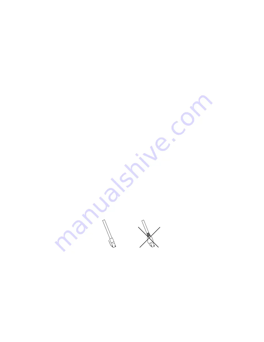
Cable Requirements
LAN cables must be ANSI/TIA-568 compliant unshielded twisted pair (UTP) with a rating of category 6 or better (CAT-6). Due to
limited space and accommodation for bend radius within an electrical box or within a tabletop stand cavity, LAN cables should be free
of protective boots or molded strain reliefs covering the cable’s plug and/or spring lock/release tab.
Yes
No
Installation
The TSC-G3 Series Touch Screen Controllers are designed for installation into electrical boxes in new work construction. In this context,
new work construction refers to electrical boxes that are installed behind the surface of a wall where all cabling, such as a LAN cable,
is routed within a wall cavity. While the TSC-G3 Series may be installed into surface-mount electrical boxes or into low voltage rings
(a.k.a. old work construction or brackets), doing so may compromise the aesthetic properties of the installation and will prevent the
Touch Screen Controller from lying flat on a wall surface.
The procedures on pages 10 through 12 describe in-wall installation of TSC-G3 Series Touch Screen Controllers into new work
construction electrical boxes.


