22
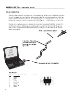
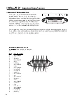
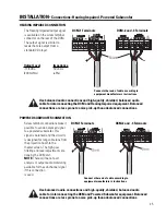
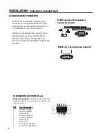
The RS-232 port is used only for setup and system troubleshooting. Connect the 9-pin serial data cable from
the host PC to this connector on the DCM. Orient the male DB9 connector to match up with the RS-232 port,
push the connector into the receptacle to seat it, and finger-tighten the retaining screws. Do not use “null-
modem”-type serial data cables; they will not work with the DCM. Use a “normal” 9-pin serial data cable.
The other end of the 9-pin serial data cable must be connected to an available RS-232 port on the host PC.
The PC must have QSC’s DCM Manager software installed on its hard drive. Start the DCM Manger pro-
gram and verify RS-232 communication between the PC and DCM. Refer to the DCM Manager software
help system for details.
RS-232 CONNECTION
Male end to DCM RS-232 Port
INSTALLATION-
Connections: RS-232
9-pin Serial Data Cable-
use normal data cable.
Do not use null-modem
type cable.
Female end to host PC RS-232 Port
RS-232 Pinout-
Configuration:
9-pin SubD male to 9-pin SubD female normal serial data cable.
Pin#
Signal Description
1
Loopback
2
Transmit
3
Receive
4
Loopback
5
Digital Ground
6
Loopback
7
Clear to Send
8
Request to Send
9
(not used)

