background image

16

LED Indicators (continued)

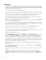
QSControl and CobraNet Network Status (Port) Indicators- 

There are two groups of three LEDs on the front and rear 

panels labeled RX, TX and


LINK. One group is for the QSControl.net network port and the other for the CobraNet network port. 

Their functions are described below. Note: Port indicators on rear panel are color coded to match the corresponding color-ring 
around the QSControl and CobraNet RJ45s.

RX 

(receive)

-

 This indicator illuminates any time the BASIS 914lz receives data from the corresponding network.

TX 

(transmit)- This indicator illuminates whenever the BASIS 914lz transmits data onto the corresponding network.

LINK STATUS-

 The corresponding indicator illuminates when the BASIS 914lz is connected to an operating network.

PORTS indicators- 

These indicators are labeled

 A

 through

 H

. These indicators are either off, red, green, or yellow, depend-

ing on what is connected to the port. The indications are:

off- nothing attached
red- QSC DSP accessory attached
green- QSC DataPort amplifier attached
yellow- QSC DSP accessory and Amplifier combination attached

LCD Display and Controls

The BASIS 914lz has a 2 line X 16 character LCD display. The display and the multi-function push-button switches on either 
side provide data access and editing capability. The push-button switches on either side of the display are used to navigate 
through the menus. The rotary select/accept knob is active for many displayed items allowing you to scroll through choices by 
rotating the control, and accepting choices (entering) by pushing in on the control.

The accessible menus and sub menus may appear differently than example shown. Software updates may occasionally 
improve the interface. Below is a the basic navigation flow for the BASIS 914lz menu system.

Front Panel Password Lockout

The password lockout provides the ability to restrict access to all of the editable parameters available on the LCD front panel. 
This feature is enabled or disabled via QSControl.net software only (refer to the “General Tab” area and click on the “Front 
Panel Password” button). when the lockout feature is enabled, all front panel LCD functions are readable, but editing of 
parameters is now password protected. While in this mode, any attempt to edit a parameter will require the user to enter the 
Front Panel Password. The default factory password is “qsc”. The password is stored in the BASIS unit and can be changed 
using the QSControl.net software.

Once the password has been correctly entered, the BASIS will allow edits to the parameters.

After 5 minutes of inactivity, the BASIS will automatically reset the Front Panel Password lockout.Re-entry of the password 
will be required to resume editing.

The lockout mode can be deliberately disabled via the “Disable Edits” screen in the Front Panel Password menu of the 
QSControl.net software.

Summary of Contents for BASIS 914lz

Page 1: ...TD 000200 00 rev B BASIS 914lz 4X16 CobraNet Enabled Control and Monitoring Signal Processor Hardware Manual TD 000200 00...

Page 2: ...cord 5 Reliable Earthing Grounding of rack mounted equipment should be maintained LITHIUM BATTERY WARNING THIS EQUIPMENT CONTAINS A NON RECHARGEABLE LITHIUM BATTERY LITHIUM IS A CHEMICAL KNOWN TO THE...

Page 3: ...interface for accessing a few critical functions A single QSControl net server computer can support several clients running QSC s latest Venue Manager software Thus the sound system can be operated v...

Page 4: ...an be easily updated over the network In the future QSC will be adding new capabilities to both BASIS and QSControl net Our latest code releases and access to up to date information on BASIS and QSCon...

Page 5: ...ing to the proper rules To learn more about CobraNet and appropriate network topologies please visit http www qscaudio com products network resources htm and http www peakaudio com CobraNet background...

Page 6: ...loyments QSControl net is a TCP IP standards compliant network system and therefore supports operation on network repeaters switches and routers When implementing the Two Wire Interface the QSControl...

Page 7: ...would have to physically connect your computer first to one BASIS box and then to the other With this elementary connection you don t have a true network It is just like making RS 232 connections exc...

Page 8: ...riate destination anywhere on the network Though the example shows only two BASIS 914lz units as many devices may be connected as there are available switch ports All BASIS units will be able to commu...

Page 9: ...ol net traffic and a separate VLAN for CobraNet audio traffic This config uration essentially provides a dedicated network for BASIS 914lz control and monitoring including the system controller and a...

Page 10: ...ith its own network switch Therefore traffic segmentation is physical rather than logical Example 5 also pro vides an additional level of fault tolerance although at the expense of additional network...

Page 11: ...ment rack Rack mounting is optional Adhesive rubber feet are included for non rack mount installations Use them to prevent the unit from scratching or marring support surfaces Rack Mounting Rack mount...

Page 12: ...ws 95 98 and ME platforms are not supported Note If system is used for real time adjustments and configuration of audio systems we recommend all Windows Power Options located in the Windows Control Pa...

Page 13: ...ntroller computer CobraNet Connection Loss If you are operating with a valid CobraNet network and the connection to the network is disrupted audio will momentarily mute allow ing the BASIS 914lz to sy...

Page 14: ...Analog Audio Inputs Four balanced combo XLR TRS inputs are provided CH 1 INPUT CH 4 INPUT They accept line level signals Plug the input signal XLR or 1 4 TRS connectors into the input receptacles Con...

Page 15: ...then push into the receptacle until it is firmly seated tighten the retaining screws finger tight LED Indicators When the BASIS 914lz is plugged into a properly functioning AC outlet it will power up...

Page 16: ...er side of the display are used to navigate through the menus The rotary select accept knob is active for many displayed items allowing you to scroll through choices by rotating the control and accept...

Page 17: ...creen accessed becomes the new power up default Boot Screen Right side buttons serve as up down navigation Arrow characters indicate right side button context If additional menus are available the arr...

Page 18: ...ecify the installation directory or accept the default location 9 You will be prompted to select an installation accessible by everyone non secure or an installation accessible only to you secure Sele...

Page 19: ...applied to the BASIS 19 Click on the sign of the BASIS 914lz in the inventory root then the sign of the Flashed Configs Click on the config with the loudspeaker icon A view of applicable device tabs...

Page 20: ...the network This is currently 16 bit 20 bit and 24 bit Audio via inbound bundles may be in any combination of these resolu tions and the BASIS will process the data accordingly All DACs will process...

Page 21: ...unicate with the BASIS 914lz if it is in safe mode You may communicate only using TFTP Telnet or RS 232 RS 232 Serial Port I O Interface The RS 232 connector on the rear panel is used as a serial port...

Page 22: ...d click OK to continue If all the connections and communications settings are correct the main Hyper Terminal window will open 6 The Hyper Terminal main window will appear next but blank Type the lett...

Page 23: ...opening a Telnet session 1 To open the Telnet session Click START select RUN type Telnet followed by a space then the IP address of the BASIS 914lz you want to communicate with in the text box and cli...

Page 24: ...u 5 7 11 8 21 3 27 3 dBV 3 5 9 5 19 1 25 1 Program Outputs 16 Connector Type 8 HD 15 dataport connections Cable Type QSC DataPort cable QSC p n DPC x x designates cable length in feet Available stock...

Page 25: ...passive resistive controls RS 232 Port Female DB9 Connector QSControl net Neutrik Ethercon RJ45 Ruggedized Data Connector CobraNet Neutrik Ethercon RJ45 Ruggedized Data Connector Indicators QSControl...

Page 26: ...26 Dimensions...

Page 27: ......

Page 28: ...ts suppliers be held liable for any damages consequential incidental or otherwise including any claims for lost profits and or savings resulting from any attempted integration of QSControl products wi...

Reviews: