background image

Attero Tech by QSC

 unBT2A 

User Manual 


 QSC, LLC 2020 


614-00034 

4 – Initial Device Setup 

*Note:

 Once the wall plate is installed in the wall, the USB port used for configuration will not be accessible. It is therefore 

recommended setup be completed before installing the wall plate into the wall. 

 
The unBT2A features software configuration and status monitoring of the following device parameters using Attero Tech's 

unIFY Control Panel software (V2.1 or later): 

o


Bluetooth® friendly name (Default: unBT2A) 

o


Mono/Stereo output selection 

o


Analog output sensitivity 

o


Pairing button control 

o


unBT2A status 

o


Remote pairing activation/deactivation 

o


Clear pairing list 

 
To access these parameters, first install and unIFY Control Panel onto a Windows PC then connect the unBT2A via the 

mini-USB connection on the unit to allow proper detection. The unIFY Control Panel software comes with the necessary 
drivers required by the operating system for compatibility with the unBT2A. Once the unIFY Control Panel application is 

open, select the “unBT2A Configuration” menu item from the “Tools” menu. Then use the drop down to select the COM 
port the BT2A is using and click the “Connect” button. 


*Note: 

Power supplied via the USB connection is enough to power the unBT2A for initial configuration. While the device 

will operate normally including allowing pairing, the audio outputs of the unBT2A will not operate while it is powered only 

via USB. If it is necessary to test the audio output while connected to the USB, connect the unBT2A-EXP and the use the 
supplied wall wart in order to fully power the device. 

 
For a complete description of the software features, refer to the BT2A section of the 

unIFY Control Panel user manual
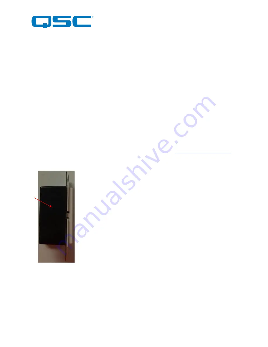
. 


4.1 – Factory Reset 

The unBT2A has a factory reset option. Using it will reset all the devices parameters back to 

their factory defaults. The devices IP address mode is also reset back to getting a dynamic IP. 
 

Access to the factory reset button is through a small circular hole on the side of the unit. 
 

To use the factory reset, be sure the unit is powered up and  insert a small screwdriver or 
paperclip into the hole to activate the factory reset switch. There should be a noticeable “click” 

when it’s activated. Hold the switch in for 5 to 10 seconds and release the switch. If the factory 
reset was successful, the left hand LED will briefly glow red and then change to green.  If not, 

the reset switch was not held in long enough. 


4.2 – Firmware Updates 

The unBT2A does support field firmware updates. Any new firmware will be made available on the Attero Tech Support 

Desk web portal. Unlike our other updatable products, the firmware file for a BT2A is provided as a .bin file. This file can 
then applied by connecting the BT2A to a PC and using the “Update Firmware” feature on the BT2A plug-in within unify 

Control Panel. 
 

*Note:

 Only the wall plate contains firmware and it must be connected to a PC via its USB interface to apply any update. 

This will necessitate removing it from the wall to access it. 
 

Summary of Contents for ATTEROTECH unBT2A

Page 1: ...erved QSC and the QSC logo are registered trademarks of QSC LLC in the U S Patent and Trademark office and other countries All other trademarks are the property of their respective owners Patents may...

Page 2: ...ularly at plugs convenience receptacles and the point where they exit from the apparatus 11 Only use attachments accessories specified by Attero Tech 12 Use only with the cart stand tripod bracket or...

Page 3: ...y energy and if not installed and used in accordance with the instruction manual may cause harmful interference to radio communications Operation of this equipment in a residential area is likely to c...

Page 4: ...uct Features 5 3 System Connectivity 8 4 Initial Device Setup 9 4 1 Factory Reset 9 5 Mounting and Installation 10 5 1 Audio Connections 11 6 Bluetooth Operation 12 7 3rd Party Control 13 7 1 RS 232 I...

Page 5: ...A EXP has an RS 232 port for 3rd party control in installations featuring an integrated control system Features o Single gang Decora form factor for easy installation in space constrained applications...

Page 6: ...cator 3 Power ID Error indicator see note below Note The unBT2A is equipped with error reporting features Upon power up the power LED will initially light red and then change to green if the device bo...

Page 7: ...LLC 2020 614 00034 Figure 2 unBT2A Rear Panel Features 4 USB Configuration Port 5 unBT2A EXP Port CAT5 6 connection for Audio Power and Control Note This is NOT a network port DO NOT connect to a netw...

Page 8: ...re 3 unBT2A EXP Features 7 RJ45 unBT2A Port CAT5 6 connection for Audio Power and Control Note This is NOT a network port DO NOT connect to a network switch 8 Balanced Audio Output Terminal Blocks 9 R...

Page 9: ...this example the analog outputs are interfaced to an audio DSP for processing and distribution throughput the venue The RS 232 is interfaced to a control system to allow extended control over the unBT...

Page 10: ...is powered only via USB If it is necessary to test the audio output while connected to the USB connect the unBT2A EXP and the use the supplied wall wart in order to fully power the device For a comple...

Page 11: ...tionally the unBT2A wall plate should also start up and once ready to operate the front panel power status indicator should also be illuminated green Note Upon power up the power LED will initially li...

Page 12: ...onnecting the outputs of the unBT2A to audio devices GND Pin 1 Pin 3 Pin 2 1 1 2 3 XLR M 2 Wire Cable Shield Or 3 Wire Cable TRS Plug GND Sleeve Tip Ring 2 Wire Cable Shield Or 3 Wire Cable Figure 7 B...

Page 13: ...0 seconds after which the status LED will stop flashing and turn off and the unBT2A will disable its Bluetooth interface Note The default friendly name visible to other devices is unBT2A This name can...

Page 14: ...available to the installer except firmware updates are also supported via the RS 232 interface The full command set that the unBT2A supports can be found in the unIFY 3rd party Software API document a...

Page 15: ...e Maximum audio output level shall be 20dBu in the 4dBu mode and 6dBu in the 10dBVmode The device shall have RS 232 real time control of pairing and other user features over a 3 pin depluggable connec...

Page 16: ...P Profile only Range Approx 10m 30ft minimum Audio Outputs Output Type Two balanced line level with automatic muting on loss of A2DP audio stream Phoenix style 3 81mm de pluggable terminal blocks Outp...

Reviews: