Page
8
of
25
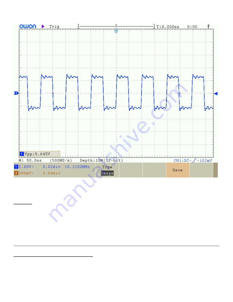
If you do NOT see a nice 5V peak-peak squarewave here on IC3 pin 8, then you have to trace back further to see why
you do not have a signal from the Si5351A Synthesiser chip (IC1). Check on pin 10 of IC3. You should see a 3.3V peak-
peak squarewave. IC3 pin 10 is connected directly to IC1 pin 6 (Clk2 output of the Si5351A). If you do not see this signal
then check for track discontinuities, check for short-circuits to ground, or to nearby pins.
EXAMPLE:
I had one repair case where the IC3 pin 10 was at 3.3V permanently, regardless of what was done with the
processor. Upon inspection of IC1 (Si5351A) with a jeweler's loupe, I could see a very tiny whisker of solder lying between
IC1 pin 6 (Clk2 output) and IC1 pin 7 (+3.3V). This was shorting Clk2 to the Si5351A's 3.3V supply, and explains why
there was no oscillator output signal from Clk2. I could easily remove the solder whisker just by briefly touching IC1 pin 6
with the soldering iron. Problem solved!
Note that this problem of Clk2 shorting to +3.3V would have caused a lot of problems on transmit. On key-down, a high
current would flow from +12V through Q6, through L4, and through the BS170 MOSFETS Q1, Q2 and Q3. Everything
would get very hot and eventually something would fry.
Signal generator injection into the front end
The size of this resistor (120K) has been chosen so that when in the "8.7 Peak BPF" menu, the ADC is not overloaded,
and a meaningful adjustment can be made. However, 120K series resistor into a 50-ohm load, which is approximately
what the impedance of the transceiver's RF in/out is, means the 5V signal is reduced by a factor of 2,400 approx. This is a
2mV signal and it gets further attenuated by losses in the BPF and the mixer... and so it is way WAY too small to be able
to view the signals on an oscilloscope.


