


Part number, Rev 2.x
Page 8
4.0
Installation
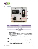
Figure 2
Item #
Description
1
External Temperature Auxiliary Jack
2
USB Output
3
Power Switch
4
Water Outlet
5
Power Cord Adapter
6
Water Inlet
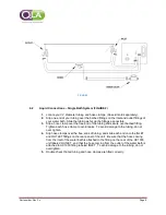
4.1
Electrical Connections
1.
Ensure power switch (SEE FIGURE 2 / ITEM 1) on the rear panel is in the OFF
position.
2.
Connect the power cord to the AC power connector (SEE FIGURE 2 / ITEM 2) on
the rear panel of the unit.
3.
Plug the other end of the cord into an outlet of the proper voltage.
The supplied power cord is standardized to the United States. Confirm that any power
cord you use meets all local safety regulations and is rated to carry at least 10 amps.
A circuit breaker triggers an automatic shutdown of the unit if a power surge occurs.
Simply switch off and restart the unit. If the problem persists, contact a QLA Lab
Services Professional or authorized QLA engineer.


