background image

12

6. Burner Setup

Good, reliable operation with a minimum of service, starts with attention to the small 

details:


Oil:

1.  Setting the nozzle  position and electrodes to the manufactures specs  using the 

manufacturer's gauges.

2.  Installing a quality micron filter at the burner.(replace old oil lines and clear sludge)

3.  Making careful/tight flare connections, without couplings, on oil suction line.

4.  Checking fuel pump pressure is set to specs on following page.

5.  Checking draft at the breeching to insure it is adequate to overcome flue gas 

resistance. (-.02 to –.04 in. w.c.)

6.  Setting the air band properly with well maintained instruments. A good target is 12% 

to 12.5% of  (CO2). 

7.  To achieve the rated efficiency level the CO2 should be set to 12.5% CO2.

To ensure proper burner setup, gauges should be used to check things such as the 

pump pressure, CO2 levels, CO levels, etc…

Gas:

1.  Checking the electrode, orifice size, and flame rod settings against manufacturer’s 

specs to insure proper operation.

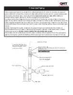
2.  Installing properly sized gas piping according to BTU input required and length of gas 

line run.

3.  Making sure there is proper manifold pressure before and after the gas valve using 

a calibrated manometer.

4.  Checking draft at the breeching to insure it is adequate to overcome flue gas 

resistance. (-.02 to –.04 in. w.c.)

5.  Setting the air band properly with well maintained instruments. A good target is 9.5% 

to 10.0% of  (CO2)  for natural gas, or 11.0% to 11.5% of  (CO2) for LP gas.

CUT INSULATION IN BLAST

TUBE OPENING TO 4.25" 

TO ACCEPT CARLIN BLAST

TUBE.

On BIASI B10 Boilers: 

TRIM INSULATION IN 

BOILER DOOR OPENING 

TO 4.25” FOR BECKETT AND 

CARLIN EZ BLAST TUBE.

Summary of Contents for Direct Vent DVF-4 Rigid

Page 1: ...low the gas supplier s instructions If you can not reach your gas supplier call the fire department Installation and service must be performed by a qualified licensed installer service agency or the g...

Page 2: ...nt Kit Gas or Oil DVF 4 Rigid Vent Kit and Installation 4 9 DVF 4 Installation of Make Up Air 4 1 10 DVF 4 Installation of Exhaust Termination 4 2 10 DVF 4 Joint Assembly 3 3 8 DVF 4 Appliance Connect...

Page 3: ...l fire hazards Please read the literature and warranties supplied by the manufacturers of the various accessory equipment This equipment is warranted by the respective manufacturers not by Quincy Hydr...

Page 4: ...with those of influenza and the highest incidence of poisoning occurs at the onset of cold weather or during flu season A victim may not experience any symptoms only one symptom or a few symptoms Susp...

Page 5: ...ce technician or gas supplier DO NOT ATTEMPT TO START THE BURNER WHEN EXCESS GAS HAS ACCUMULATED WHEN THE UNIT IS FULL OF VAPOR OR WHEN THE COMBUSTION CHAMBER IS VERY HOT NOTE ALWAYS KEEP THE MANUAL F...

Page 6: ...Vent hood shall be installed 12 above ground level or 12 above nominal snow level of the region of the installation which ever is higher 2 The Vent hood shall not be less than 3 feet above any forced...

Page 7: ...3 DVO Flexible Vent Kit and Installation Vent Installation 1 Vent Pipe bend radius is 12 minimum 2 Support vent pipe with metal strapping every 36 3 Maximum wall thickness is 14 Call Z Flex for recom...

Page 8: ...From outside the building insert the outer section through the wall until it rests against the wall Position the outer section so that the air intake is on the bottom Secure to outer wall using four...

Page 9: ...und the flue collar and slide on adaptor and tighten gear clamp 4 Seal the seam on the adaptor 5 Slide the terminal inner section over the terminal outer section and secure by tightening the gear clam...

Page 10: ...on to the outer sleeve to complete the joint assembly 3 3 DVO Joint Assembly APPLIANCE CONNECTION 1 Connect the appliance adapter to the appliance collas as per joint assembly 2 Apply Sealant around...

Page 11: ...e provisions do not exist for the ducting of combustion products to the outside The direct vent connector shall not pass through any floor or ceiling The burner exhaust must be ducted directly to the...

Page 12: ...s been determined cut a 8 hole for a non combustible wall or a 9 hole for a combustible wall Using 2 X 2 Frame a box around the hole on the outside of the house so the flange is mounted away from the...

Page 13: ...electrically bonded to ground in accordance with the requirements of the authority having jurisdiction or in the absence of such requirements with the National Electrical Code ANSI NFPA 70 or Canadian...

Page 14: ...hould be set to 12 5 CO2 To ensure proper burner setup gauges should be used to check things such as the pump pressure CO2 levels CO levels etc Gas 1 Checking the electrode orifice size and flame rod...

Page 15: ...er Model EZ Select EZ Select EZ Select EZ Select Firing Rate 50 78 1 06 1 33 Insertion Depth 3 0 3 0 3 0 3 0 Nozzle 40x45 65X70 85X60 1 00X60 Spray Pattern A A A B Pump Pressure 155 psi 150 psi 150 ps...

Page 16: ...am and controls To determine how much gas is coming into the burner or to set the gas meter correctly the following formula can be used The chart to the right can be used to determine the flow rate de...

Page 17: ...r the tee before the combination gas valve When installing the boiler make sure a pipe compound resistant to the action of liquefied petroleum is used Check piping for leaks Always check leaks with a...

Page 18: ...16 8 Wiring Oil Burners NOTE All wiring must be done in accordance with applicable state local and national codes Use only copper conductors...

Page 19: ...17 9 Wiring Gas Burners NOTE All wiring must be done in accordance with applicable state local and national codes Use only copper conductors...

Page 20: ...n to inspect the appliance and to replace any part of the control system and any gas control which has been under water OPERATING INSTRUCTIONS 1 STOP Read the safety information above 2 Set thermostat...

Page 21: ...er of any debris with brush and vacuum 4 Remove smoke pipe and clean out debris from cleaning or soot build up 5 Inspect smoke pipe for any corrosion before reinstalling Replace if necessary 6 Consult...

Page 22: ...mp Room Temp Ambient Net Stack Temp CO2 O2 Smoke Reading Combustion EFF System Checklist Boiler Model Serial Original Purchaser Installer Burner Checklist Burner Manufacturer Burner Fuel Type Burner M...

Page 23: ...21 13 Installer Notes Continued Comments Notes...

Page 24: ...HVAC products sold to wholesale distributors in the U S and Canada Customer service and support are the key to QHT s business From troubleshooting radiator piping to working through problems with wal...

Reviews: