background image

NOTE: This equipment has been tested and found to comply with the limits for a 
Class B digital device, pursuant to part 15 of the FCC Rules. These limits are 

designed to provide reasonable protection against harmful interference in a 

residential installation. This equipment generates uses and can radiate radio 

frequency energy and, if not installed and used in accordance with the instructions, 

may cause harmful interference to radio communications. However, there is no 

guarantee that interference will not occur in a particular installation. If this 

equipment does cause harmful interference to radio or television reception, which 

can be determined by turning the equipment off and on, the user is encouraged to 

try to correct the interference by one or more of the following measures: 


- Reorient or relocate the receiving antenna. 

- Increase the separation between the equipment and receiver. 

-Connect the equipment into an outlet on a circuit different from that to which the 

receiver is connected. 

-Consult the dealer or an experienced radio/TV technician for help 


Changes or modifications not expressly approved by the party responsible for compliance  

could void the user's authority to operate the equipment.   This device complies with Part 

15 of the FCC Rules.  Operation is subject to the following two conditions:  

(1) this device may not cause harmful interference, and  

(2) this device must accept any interference received,  including interference that may 

cause undesired operation.  


Summary of Contents for TURN-200

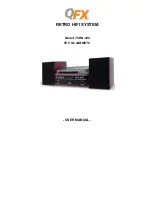
Page 1: ...RETRO HIFI SYSTEM Model TURN 200 FCC ID 2ABM9T9 USER MANUAL...

Page 2: ...t hands To avoid electric shock NEVER touch any internal parts Repairs Servicing should be left to a qualified service person When connecting or disconnecting from the mains supply hold the plug not t...

Page 3: ...agnitude to constitute a risk of electric shock to persons The exclamation point within a triangle indicates the presence of important operating and maintenance servicing instructions in the literatur...

Page 4: ...ates a safety interlock mechanism which switches the laser beam on and off so that when the disc holder is open the laser beam stops automatically This set employs an optical laser beam system in the...

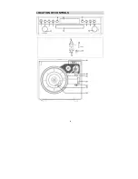
Page 5: ...4 LOCATION OF CONTROLS...

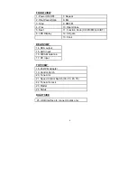
Page 6: ...M AUX BT 6 LED Display 12 CD gate 13 Vol REAR VIEW 14 RCA output 15 AUX input 16 FM AM Antenna 17 DC input TOP VIEW 18 45 RPM Adapter 19 Control Perch 20 Tone Arm 21 Speed Control Switch 33 1 3 45 78...

Page 7: ...nect the 2 speakers with the main unit Connect the DC Power adapter to the DC outlet Unwind the FM antenna Adjusting the sound To adjust the sound rotating the Volume Knob located on the right side of...

Page 8: ...ause LED screen will indicate II Press STOP Button it will stop playing To resume play press the PLAY PAUSE Button again Press the PREV or NEXT Button to enter into last next songs USING THE TURNTABLE...

Page 9: ...eplace the needle please refer to the instructions below Removing the needle form the cartridge a Place a screwdriver at the tip of the needle heads hell and push downwards in the direction shown in s...

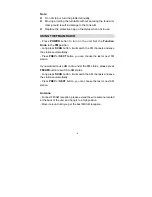
Page 10: ...he FM channels and save the stations automatically Press PREV or NEXT button you can choose the last or next FM station If you wanted to use AM radio under the FM status please press FM AM button to s...

Page 11: ...ATION Press POWER button to turn on the unit Set the Function Knob to the BT Bluetooth position It will show flashing BLUE on the LED display Open the BT mode on your mobile phone or other Bluetooth e...

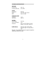
Page 12: ...n 35dB SPEAKER SYSTEM Impedance 2 ohm Input Power Max 5W GENERAL Power Supply DC 5V 2A Power Consumption 10W Dimension Main unit L320 x W278 x H160 mm Speaker L140 x W210 x H210 mm BLUETOOTH 2 1 Bluet...

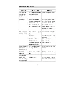
Page 13: ...n to increase the volume The CD player does not work Disc is inserted upside down Disc is dirty Disc is scratched Disc is warped A non standard disc is inserted DVD VCD Insert the disc correctly Wipe...

Page 14: ...e determined by turning the equipment off and on the user is encouraged to try to correct the interference by one or more of the following measures Reorient or relocate the receiving antenna Increase...

Reviews: