background image

SAFETY & REGULATORY INFORMATION 

Network Switch Installation Guide  

8


may accept any interference received, including interference that may cause undesired 
operation. 
This equipment has been tested and found to comply with the limits for a Class A digital 
device, pursuant to part 15 of the FCC Rules. These limits are designed to provide 
reasonable protection against harmful interference when the equipment is operated in a 
commercial environment. This equipment generates, uses, and can radiate radio 
frequency energy and, if not installed and used in accordance with the instruction 
manual, may cause harmful interference to radio communications. However, there is no 
guarantee that interference will not occur in a particular installation. If this equipment 
does cause harmful interference to radio or television reception, which can be determined 
by turning the equipment off and on, the user is encouraged to try to correct the 
interference by one or more of the following measures: 


Reorient or relocate the receiving antenna. 


Increase the separation between the equipment and the receiver. 


Connect the equipment to an outlet on a circuit other than the one to which the 
receiver is connected. 


Consult the dealer or an experienced radio/TV technician for help. 

Any changes or modifications not expressly approved by the grantee of this device could 
void the user’s authority to operate the equipment. The customer is responsible for 
ensuring the compliance of the modified product. 
Only peripherals (computer input/output devices, terminals, printers, etc.) that comply 
with FCC Class A or B limits may be attached to this computer product. Operation with 
noncompliant peripherals is likely to result in interference to radio and TV reception. 
All cables used to connect to peripherals must be shielded and grounded. Operation with 
cables, connected to peripherals, that are not shielded and grounded may result in 
interference to radio and TV reception. 
 

Europe (CE Declaration of Conformity) 1.5.1.2 

This product has been tested in accordance to, and complies with the Low Voltage 
Directive (73/23/EEC) and EMC Directive (89/336/EEC). The product has been marked 
with the CE Mark to illustrate its compliance. 
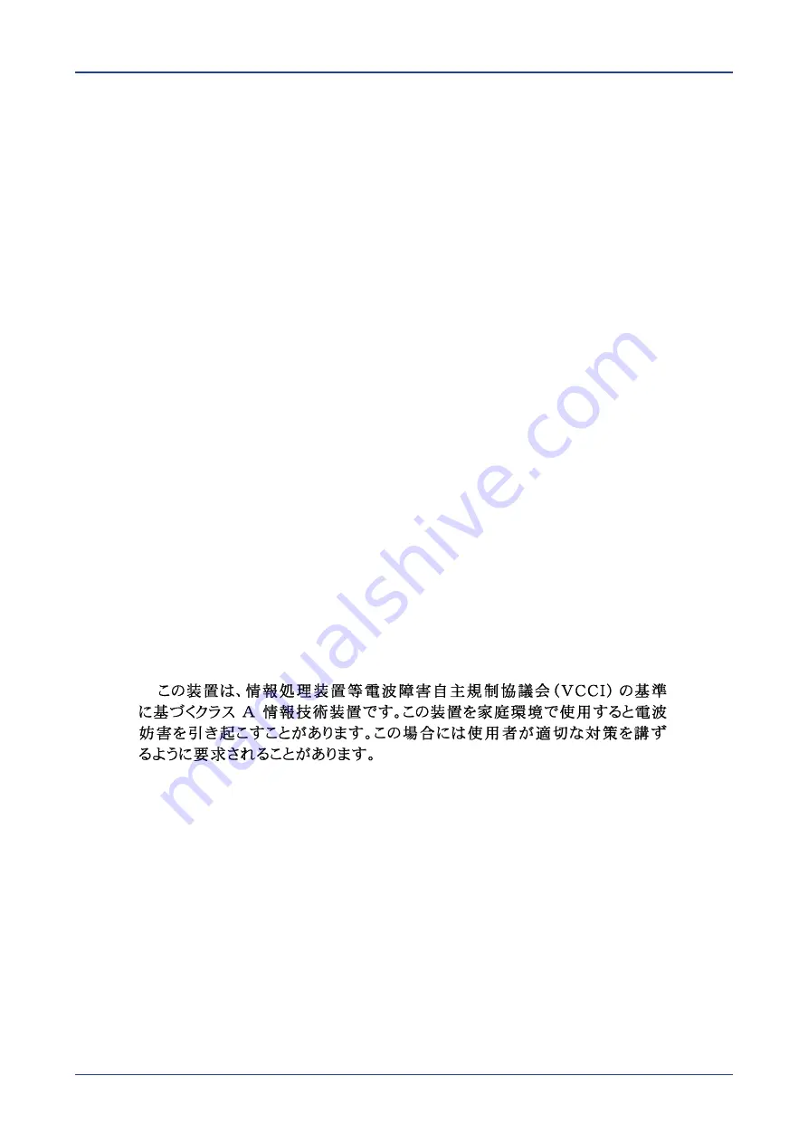
 

VCCI (Japan) 


English translation of the notice above: 
This is a Class A product based on the standard of the Voluntary Control Council for 
Interference (VCCI) from Information Technology Equipment. If this is used near a radio 
or television receiver in a domestic environment, it may cause radio interference. Install 
and use the equipment according to the instruction manual. 

CCC Statement 

声明


此为

A

级产品,在生活环境中,该产品可能会造成无线电干扰


在这种情况下,可能需要用户对其干扰采取切实可行的措施


Regulated Specified Components 

To maintain the UL listing and compliance to other regulatory certifiications and/or 
declarations, the following regulated components must be used and conditions adhered 

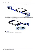
Summary of Contents for QuantaMesh T1048-LB9M

Page 1: ...QuantaMesh T1048 LB9M Network Switch Installation Guide...

Page 2: ......

Page 3: ...nology Equipment ITE which may be installed in offices schools computer rooms and similar commercial type locations The suitability of this product for other product categories and environments such a...

Page 4: ...ly be serviced by trained service technician If any of the following conditions occur unplug the equipment from the electrical outlet and replace the part or contact a trained service technician The p...

Page 5: ...ion cable with properly grounded plugs Observe extension cable and power strip ratings Ensure that the total ampere rating of all products plugged into the extension cable or power strip does not exce...

Page 6: ...ack kit The rail racks are designed to carry only the weight of the system Do not place additional load onto any rail mounted equipment System rack kits are intended to be installed in a rack by train...

Page 7: ...e power cord to the power supply being replaced before removing it from the switch Power Cord Warnings If an AC power cord was not provided with your product purchase one that is approved for use in y...

Page 8: ...the system without the fan guard in place Rack Mount Warnings The following installation guidelines are required by UL for maintaining safety compliance when installing your switch into a rack The equ...

Page 9: ...otherwise damage a battery Cooling and Airflow CAUTION Carefully route cables as directed to minimize airflow blockage and cooling problems For proper cooling and airflow operate the system only with...

Page 10: ...expressly approved by the grantee of this device could void the user s authority to operate the equipment The customer is responsible for ensuring the compliance of the modified product Only periphera...

Page 11: ...and TUV and VDE licensed Maximum power rating of any one device is 19 watts Total server configuration is not to exceed the maximum loading conditions of the power supply Restriction of Hazardous Sub...

Page 12: ...mplies with Part 15 of the FCC Rules Operation of this device is subject to the following two conditions 1 This device may not cause harmful interference and 2 This device must accept any interference...

Page 13: ...n 19 Hardware Installation 20 Unpacking the Hardware 20 Package Contents 20 Installing the Switch 20 Site Survey 20 Positioning the Switch 21 Rack Mounting the Switch 21 Connecting to the Console Port...

Page 14: ...a center as the rack management switch With QNOS supported QuantaMesh T1048 LB9M offers the complete layer2 layer3 functions which are right fit for contemporary data center Chassis for the T1048 LB9M...

Page 15: ...QuantaMesh T1000 Series 13 Network Switch Installation Guide Rear panel No Item No Item 1 PSU LEDs 4 Fan LEDs 2 PSU2 5 Fixed Fan Modules 3 AC Power Connector with Plug Retainer 6 PSU1...

Page 16: ...itch is loading the agent software code FAN LED front panel bi color green red LED number One per system on the front panel Off None Red Solid Any one of fans is not operating well Red Blinking None G...

Page 17: ...ne RJ45 GE Port Link Activity LED bi color green amber LED number One per port on the right each port Off No link Amber Solid None Amber Blinking None Green Solid The port is linked Green Blinking The...

Page 18: ...t attached cable For more information on obtaining the appropriate SFP28 modules refer to Supported Cables and Transceivers The management port enables you to manage the switch operation using an RJ 4...

Page 19: ...of T1048 L SFP28 Port Connection The switch is equipped with 4 SFP28 ports designed for 25Gbps data rate The SFP28 ports support 25 Gigabit Ethernet following IEEE 802 3ae Ethernet for fiber mediums T...

Page 20: ...direction label on the rear panel to determine its airflow direction Red indicates front to back airflow Blue indicates back to front airflow The AC power connector is a standard three pronged connec...

Page 21: ...t to Back Airflow The air intake is located on the front panel of the switch The cool air is sucked in from outside the chassis and pushed toward the rear of the chassis The hot air exhausts through t...

Page 22: ...flat and stable surface and cut the straps securing the box 2 Carefully remove the switch Then place it on a flat and clean surface 3 Remove all other items from the box and inspect each item Install...

Page 23: ...l on the rear panel to determine its airflow direction Red indicates front to back airflow air inlet module See Front to Back Airflow Blue indicates back to front airflow air outlet module See Back to...

Page 24: ...ward to release the inner rail from the middle rail Remove the inner rail NOTE Repeat the similar steps to remove another inner rail 2 Pull the tab upward to unlock the latch and then push the middle...

Page 25: ...les on the rail mounting brackets with the switch 7 Secure the rail mounting brackets with screws 8 Align the hooks on the switch with the holes in the inner rail and then slide the inner rail backwar...

Page 26: ...install the rear bracket Align and push the rail firmly into the rear rack until it clicks into place Make sure the L shaped bracket is facing inward 11 Pull the middle rail out until it is fully exte...

Page 27: ...on Below is the console cable wiring specification table RJ 45 Port of Switch DB9M Female Port of PC Abbreviation Description 3 2 RD Received Data 6 3 TD Transmit Data 1 8 CTS Clear To Send 8 7 RTS Re...

Page 28: ...and data rate can be in 10Mbps 100Mbps or 1Gbps Telnet SNMP and Web browser utility can all go through this port for local or remote management after the IP address subnet mask and default gateway ar...

Page 29: ...a time Two circuits provide redundancy protection NOTE Each PSU has an AC power connector At least one power supply must connect to a power source Connecting the Power Source To connect the switch to...

Page 30: ...rt module PSU PSU1 PSU2 LED is in Red state Possible issues Fan Lock 15 sec OTP Over Temperature Process OCP Over Current Process OVP Over Voltage Process UVP Under Voltage Process Fan LED is in Red s...

Page 31: ...pply will cause the switch to automatically shut down The PSU s can be replaced without the use of special tools Before replacing any of the PSUs verify the status of the PSU to determine if there is...

Page 32: ...e are no user serviceable parts inside the PSU Do not disassemble any part of the PSU Doing so voids the warranty and regulatory certifications For maintenance services not mentioned in this guide ple...

Page 33: ...of different protocols i e FTP TFTP and HTTP to download the installer file from your local server To download and update the vendor OS code manually perform the following 1 Locate the specific QUANT...

Page 34: ...t 4 In ONIE Linux shell use the install_url command to update the vendor OS code Use one of the following commands install_url tftp 192 168 2 153 ly3 onie installer 1 5 3 or install_url ftp 192 168 2...

Reviews: