background image

A

BOUT


THE

 S

YSTEM

A T

OUR


OF


THE

 S

YSTEM

 1-8

Power Supply Unit

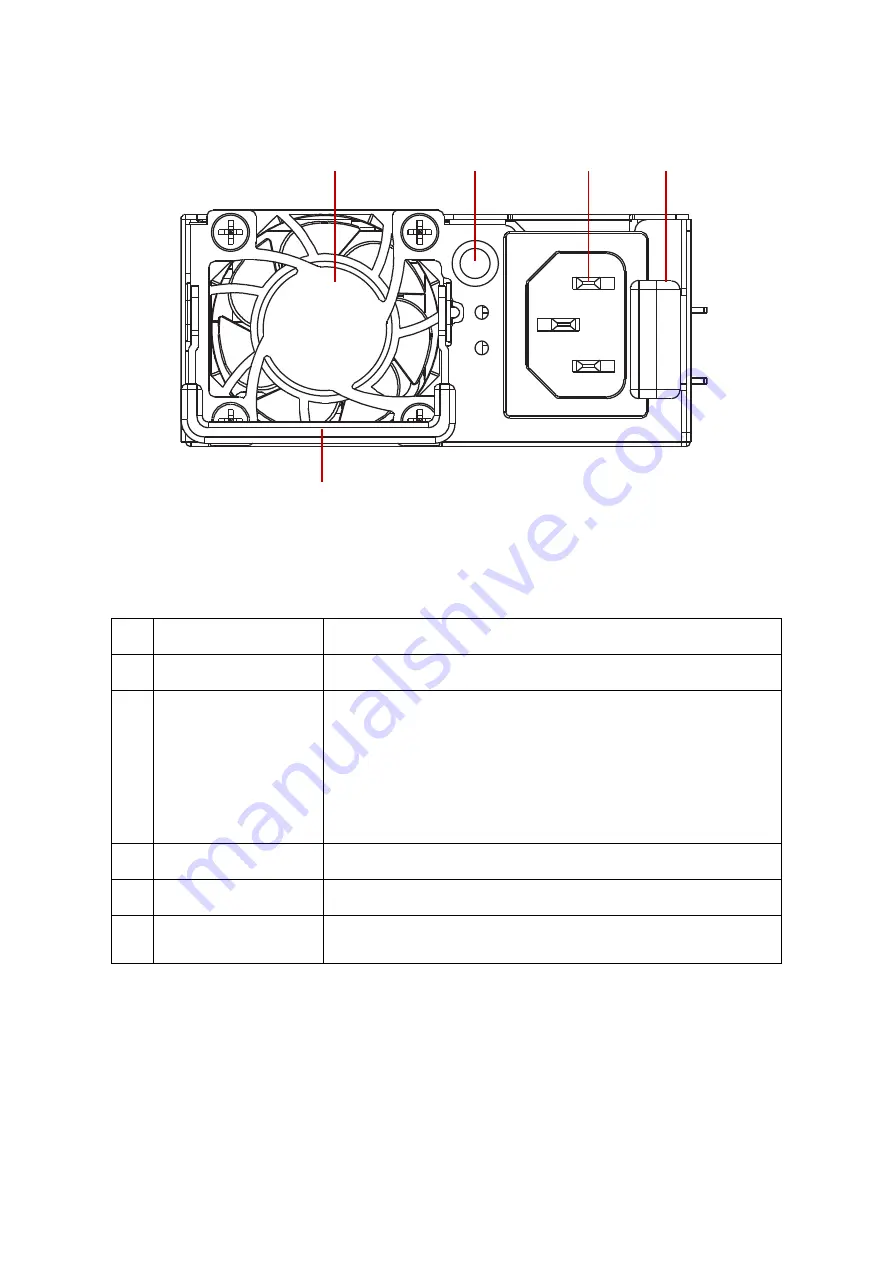
Figure 1-6.

Power Supply Unit Overview

Note:

The message shown on the CLI console for PSU installed to system will be [Normal] 
if the power cord is disconnected. Cold redundant is available when showing [Mas-
ter] or [Slave]on CLI console for the PSU installed.

Table 1.6: PSU rear view

N

O

.

N

AME

D

ESCRIPTION

1

Fan

Cooling the Power Supply Unit (PSU).

2

PSU  LED

Lights for PSU status. 

Off: No AC power

Amber On: Failed

Green On: Status Good

Green Blinking (1 sec/on, 1 sec/off, 0.5Hz) :  Standby Mode

Green Blinking (0.5 sec/on, 0.5 sec/off, 2Hz): Sleep PSU in Cold 
Redundant / Off Mode

3

Socket

Connects to power cord.

4

Latch

Press to release the latch.

5

Handle

Pull out and hold the handle with hands for removing the PSU from the 
chassis bay.

1

2

3

5

4

Summary of Contents for JB4242

Page 1: ...Version 1 0 QuantaVault Series JB4242 High Density 4U Disk Expansion Unit User s Guide...

Page 2: ...em 1 4 System Front View and HDD Location 1 4 Front Control Panel 1 5 Front Loading Carrier 1 6 System Rear View 1 6 Rear Loading Carrier 1 7 Power Supply Unit 1 8 System Fan and SSD Fan Module 1 9 SA...

Page 3: ...ers Version 1 0 January 20 2016 Disclaimer The information in this document is subject to change without notice The manufacturer makes no representations or warranties with respect to the contents her...

Page 4: ...m Intended Application Uses This product was evaluated as Information Technology Equipment ITE which may be installed in offices schools computer rooms and similar commercial type locations The suitab...

Page 5: ...ns and the names of the folders menus programs and files Enter type face denotes keyboard keys WARNING Warning information appears before the text it references and should not be ignored as the conten...

Page 6: ...bout the System This section introduces the system its different configuration s and the main features Chapter 2 Regulatory and Compliance Information This section provides regulatory and compliance i...

Page 7: ...About the System Chapter 1 This section introduces the system its different configuration s and the main features...

Page 8: ...inates unnecessary features and positioned itself as a pure storage server powered by QuantaVault solution Bring You the Most Scale Up with Daisy Chain Design QuantaVault JB4242 not only lowers the co...

Page 9: ...SD modules LED Indicators Front Control Panel System Power Status ID LEDs Storage Drive Bay Identify Status LED Activity LED PSU Status LED Fan Status LED SAS Interface Module SIM Power Status ID LEDs...

Page 10: ...BOUT YOUR SYSTEM PACKAGE CONTENTS 1 3 1 2 Package Contents 1x JB4242 system 2x power cords optional 1x utility disc 1x rail kit Note For exact shipping contents contact your local sales representative...

Page 11: ...Panel Control Panel includes the following LEDs Buttons Power Button with LED Status LED ID button ID LED 2 Thumb Screw Secure the system to the rack 3 Handle Hold with care and extend out the system...

Page 12: ...urn on off the system Lights for system power status Blue On Power On Off Power Off 2 Status LED Lights for system status Amber On System Failed Amber Blinking two times per sec Rear SSD Failed Amber...

Page 13: ...ION 1 Handle Hold and pull the carrier out with care The handle is not designed to carry the storage drive 2 Release button Press to release the handle 3 Activity LED Lights for Activity status Blue O...

Page 14: ...ll the carrier out with care The handle is not designed to carry the storage drive 2 Release button Press to release the handle 3 Present Fault LED Lights for Present Fault status Blue On Present Blue...

Page 15: ...for the PSU installed Table 1 6 PSU rear view NO NAME DESCRIPTION 1 Fan Cooling the Power Supply Unit PSU 2 PSU LED Lights for PSU status Off No AC power Amber On Failed Green On Status Good Green Bli...

Page 16: ...rheating replace the fan module within 10 minutes Table 1 7 System Fan and SSD Fan Module overview NO NAME DESCRIPTION 1 Latch Press to release the latch of SSD fan module 2 Handle Pull out and hold t...

Page 17: ...PHY s Link Failed Off Status Good 4 Activity LED Lights for mini SAS HD port activity LED Blue On Connected Off Disconnected 5 Link LED Lights for management port link LED Amber On 1000Mbps connection...

Page 18: ...T THE SYSTEM A TOUR OF THE SYSTEM 1 11 9 Status LED Lights for SIM status Amber On Failed Off Status Good 10 Power LED Lights for SIM power Blue On Power On Off Power Off Table 1 8 SIM overview Contin...

Page 19: ...ode Two zone mode has 2 mini SAS HD host ports 4 SSDs and 12 HDDs as shown for each zone as shown Figure 1 9 Zoning configuration Two zones mode Note SIM 1 does not support SATA device status Front Vi...

Page 20: ...Regulatory and Compliance Information Chapter 2 This section provides regulatory and compliance information applicable to this system...

Page 21: ......

Page 22: ......

Page 23: ......

Page 24: ......

Page 25: ......

Page 26: ......

Page 27: ...A VCCI A A...

Page 28: ...A VCCI A A...

Page 29: ......

Reviews: