background image

36

37

CHAPTER 4  MAIN MENU SETUP

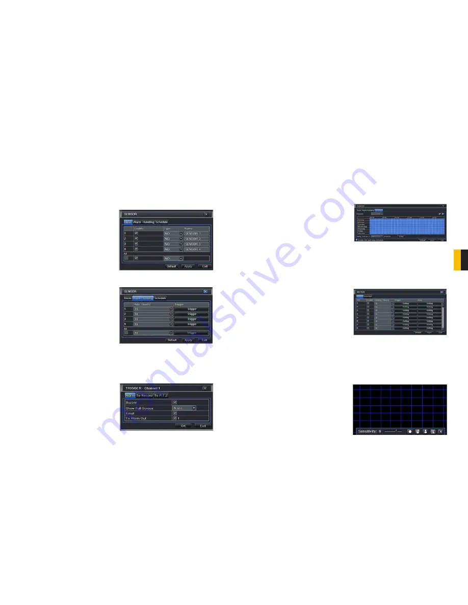
PICTURE 4-24

PICTURE 4-25

PICTURE 4-26

4.5 ALARM CONFIGURATION

Alarm configuration allows the DVR to begin recording based on input from other remote 
sensors such as infrared motion detectors or contact alarms which are connected to it.
There are five submenus; 

Sensor

Motion

Video Loss

Other

, and 

Alarm Out

.

SENSOR 

In this window you can setup optional external sensors to cause the DVR to begin recording. 
There are three tabs in this window: 

Basic

Alarm Handling

 and 

Schedule

.

Basic Tab

This allows you to enable the input from 
attached sensors. You can also identify the 
sensors by name for ease in determining 
location.
Set the alarm type according to whether the 
alarm is NO (Normally Open) or NC (Normally 
Closed). See your alarm’s manual for details.
Alarms can be individually configured or 
globally set using the 

All

 button.

Alarm Handling Tab

Configure how you want the DVR to handle 
the input from an activated alarm. Each 
sensor input can be set to launch individual 
sequences of action or they may be globally 
set through the 

All

 button to have the same 

results.

Hold Time:

 determines the time allowed 

between consecutive alarm events. 
If the alarm is triggered again within 
this time, it will be treated as a single 
event and the DVR will continue 
recording before stopping – unless, 
of course, a subsequent alarm is 
activated within the hold time.

Trigger:

 This is what the DVR will do once 

activated by an alarm. Selecting 

Setting

 will open a new window with 

three tabs; 

Alarm

To Record

To 

PTZ


Alarm

 allows you to set whether a 

buzzer will sound, which camera (if 
any) will display in full screen mode, 
whether an e-mail will be sent and 
whether a signal will be sent via the 
ALARM OUT port.

MOTION

Motion Tab

As with the 

Alarm

 function above, it incorporates hold time and can trigger procedures. 

Select which cameras you wish to start recording on motion detection. Set the holding time 
which determines the length of time the cameras continue recording after motion stops. 


To Record

 allows you to determine which cameras will begin recording. Cameras can 

be set to record individually, in blocks, or all cameras can be activated.


To PTZ

 activates preset, cruise or track functions on selected Pan-Tilt-Zoom 

cameras. Depending on your model of PTZ camera, one of up to 128 pre-set actions 
can be engaged. Check your camera’s manual for details.

Schedule Tab

Set by default to always on, the schedule can be altered in the same manner as that used in  

Schedule

 in 

SECTION 4.4

.

PICTURE 4-27

PICTURE 4-28

PICTURE 4-29

In the 

Trigger

 setting, you can set multiple 

channels to record when motion is detected 
by a camera that has been set to activate 
upon motion detection.

For example:

 If Camera 1 detects motion, 

you can have it trigger Cameras 2 and 3 to 
begin recording as well.

In addition, the user can set the sensitivity of certain areas within the field of view by selecting 
the 

Area 

setting for the respective camera. 

Specific areas can be made sensitive by 
applying a blue grid to the desired section of 
the screen. The blue grid can be applied to 
the entire screen – signifying that the entire 
field of view is sensitive - by clicking on 
the 

star button

. The 

trash can

 button will 

remove the grid completely. Click and drag 
with the mouse on the screen to draw or 
erase the grid in select areas. 

 As sensitivity is influenced by color and light 
level, you can adjust its values according to 
your specific conditions. The default value is 
“4.” A setting of “8” is most sensitive while a 
setting of “1” is minimally sensitive. 

Summary of Contents for QT504

Page 1: ...1 User Manual QT5 Series Network DVR With Real Time D1 Recording MODEL QT504 QT518 QT5116 QT528 QT526 QT536...

Page 2: ...to warranty and technical support benefits you ll receive notifications of product updates along with free downloadable firmware updates for your DVR Register today at www Q See com Please see the ba...

Page 3: ...ation 36 Sensor 36 Motion 37 Video Loss 38 Other Alarm 38 Alarm Out 39 4 6 Network Configuration 40 4 7 User Management 44 4 8 Pan Tilt Zoom PTZ Configuration 45 4 9 Advanced 48 Time Search 49 Event S...

Page 4: ...erate this DVR without the cover securely in place Do not attempt to do any repairs to the DVR yourself If there are unusual sounds or smells coming from the DVR unplug it immediately and contact Q Se...

Page 5: ...ports multi screen simultaneous playback Supports deleting and locking the recorded files one by one Supports remote playback in Network Client through LAN or internet ALARM 1 4 channel alarm output a...

Page 6: ...ns for up to 8 external sensors 4 NET Network ethernet port 5 VGA PORT VGA output for 19 or larger monitor 6 VIDEO OUT BNC connector for telvision or monitor 7 VIDEO IN BNC connectors for up to 8 came...

Page 7: ...TZ mode 10 INFO Displays system information 11 BACKUP Enter Backup mode Decreases the value in Setup mode 12 AUDIO Mutes or unmutes audio 13 PTZ Enter PTZ mode ITEM NAME FUNCTION 1 PTZ Connections for...

Page 8: ...us 11 RETURN Confirms selection 12 USB PORT Used for external USB backup devices The mouse will not function in this port ITEM NAME FUNCTION 1 VIDEO OUT BNC connector for telvision or monitor 2 SPOT O...

Page 9: ...ard STOP Quits Playback mode 17 CONTROL KNOB Outer ring navigates through menus Inner knob increases or decreases speed of fast forward or rewind ITEM NAME FUNCTION 1 VIDEO OUT BNC connector for telvi...

Page 10: ...Rewind PLAY Opens the Playback interface Pauses or resumes playback FF Fast Forward STOP Quits Playback mode 17 CONTROL KNOB Outer ring navigates through menus Inner knob increases or decreases speed...

Page 11: ...17 CONTROL KNOB Outer ring navigates through menus Inner knob increases or decreases speed of fast forward or rewind 3 5 7 4 1 2 6 9 8 10 11 12 14 16 13 17 15 16 BACK PANEL ITEM NAME FUNCTION 1 VIDEO...

Page 12: ...igure your DVR using the mouse controls reserving the remote control for operations such as live viewing file search and playback It uses two AAA sized batteries If the remote s performance degrades c...

Page 13: ...Control Bar Menu Volume Adjust volume This is only available if you have attached a microphone or audio capable camera to the DVR PTZ Opens the controls for optional Pan Tilt Zoom cameras Snapshot Ca...

Page 14: ...dditional commands available to you Previous Next Record Moves to the prior or following recorded event respectively Fast Forward Rewind In addition to their normal operation clicking on these buttons...

Page 15: ...channels between 1 and 16 depending on your model to display the live feeds Click the box to confirm the settings before closing the CHANNEL SELECT menu by clicking on the button MAIN MENU Selecting t...

Page 16: ...to set camera names and adjust picture colors brightness hue saturation and contrast for optimal picture results PICTURE 4 9 PICTURE 4 10 You can individually name cameras by highlighting the field f...

Page 17: ...ther Configure the recording settings for your cameras There are five sets of options Enable Record Bitrate Time Stamp and Recycle Record Enable Tab Select some or all of the cameras to record to the...

Page 18: ...E 4 23 4 4 SCHEDULE CONFIGURATION Your DVR is configured to record whenever motion is detected If this is your desired setting then you will not need to make any changes However you may configure each...

Page 19: ...whether a signal will be sent via the ALARM OUT port MOTION Motion Tab As with the Alarm function above it incorporates hold time and can trigger procedures Select which cameras you wish to start rec...

Page 20: ...s that you wish to occur in the event that a video input is lost Both Alarms and PTZ events can be scheduled as in the Sensor menu above OTHER ALARM In this menu you can set the DVR to alert you to a...

Page 21: ...e TEST button will verify that your information is correct NOTE The default value is 80 If port 80 is already occupied by another device on the network then another port will need to be selected Choos...

Page 22: ...rts It is strongly advised that you do not use the same address that the DVR is using to send alerts PICTURE 4 37 Advanced Attaching Image Amount The alert e mails can include up to three images Snap...

Page 23: ...ton Modify a user s password The admin password may be changed The default is 123456 4 8 PAN TILT ZOOM PTZ CONFIGURATION If you are connecting optional Pan Tilt Zoom cameras the controls are set from...

Page 24: ...all the way to the top of the order Move a preset point up one position in the list Move a preset point down one position in the list Move a preset point to the bottom of the order Cruise Selecting a...

Page 25: ...obile or external storage devices and recorded onto the DVR PICTURE 4 50 4 10 FILE SEARCH PLAYBACK AND MANAGEMENT Access the recordings on the DVR play them back and backup the recordings to an extern...

Page 26: ...and the word Writing disappears 2 3 4 1 6 7 8 5 SEARCH Search Time Search Image Event Search File Management Search Delete Delete Lock Lock Save Save Save All Save All Time Search Image Event Search F...

Page 27: ...mmary of the number of files starting and ending times total size of the files and whether you have space available on the receiving storage media You can select which type of device you are recording...

Page 28: ...the list of online users Disconnect The Administrator can disconnect a selected user from the DVR That PC will not be able to access the device for five minutes thereafter 6 2 MANUAL ALARM This displ...

Page 29: ...placement easy for the average user A 5400RPM drive will work but a 7200RPM drive is recommended for optimal performance It should be noted that while this is the only user serviceable part within the...

Page 30: ...for calculating the required disk space is Total Recording Capacity Used space per hour MB h x Recording time hour x number of channels Example A customer is using the NTSC format 30 frames per secon...

Page 31: ...d displays please wait all the time a First possible reason hard drive power cable and or data cable are not securely connected Solution Please check the cable connections and make sure they are secur...

Page 32: ...SSION Compression Format Standard H 264 Baseline VIDEO Video In Composite 1 0V p p 75 BNC x 8 Composite 1 0V p p 75 BNC x 16 Composite 1 0V p p 75 BNC x 4 Video Out COMPOSITE 1 0V p p 75 BNC x 2 VGA x...

Page 33: ...on Format Standard H 264 Baseline VIDEO Video In Composite 1 0V p p 75 BNC x 8 Composite 1 0V p p 75 BNC x 16 Composite 1 0V p p 75 BNC x 16 Video Out COMPOSITE 1 0V p p 75 BNC x 2 VGA x 1 HDMI Loopou...

Page 34: ...OR COMMENTS CONTACT US Digital Peripheral Solutions Inc 8015 E Crystal Drive Anaheim CA 92807 PRODUCT SUPPORT DOWNLOADS FIRMWARE UPDATES MANUALS 24 7 Technical Resources Live Chat M F 9 5 PST www Q S...

Reviews: