background image

100

101

ALARM OUT

Set how the alarms are handled and transmitted in this window. This controls any device 
attached to the ALARM OUT port on the back of the DVR. There are three tabs; 

Alarm Out

Schedule

 and 

Buzzer

.

Alarm Out Tab

You can set the relay alarm out name as well as the hold time. Hold time is the interval 
between consecutive alarm activations so multiple events within the interval will not cause the 
alarm to sound again.

Schedule Tab

The default setting is for the ALARM OUT to be active all the time, but this can be changed 
to meet your particular requirements in a similar manner to 

Schedule

 in 

SECTION 4.4

.

Buzzer Tab

As with the 

Alarm Out 

hold time, the internal buzzer can be enabled and given a hold time.

PICTURE 8-13

HARD DISK DRIVE

CHAPTER 9

Your DVR uses a standard desktop or 3.5” SATA (Serial Advanced Technology Attachment) 
hard disk drive and will support drives up to 2TB (terabytes). These drives are the current 
industry standard and may be purchased wherever computer parts are sold. Depending on 
where you purchased your DVR, your hard drive may already be installed. But, we recognize 
that you may wish to upgrade or replace your drive in the future so this DVR is designed to 
make installation and replacement easy for the average user. A 5400RPM drive will work but a 
7200RPM drive is recommended for optimal performance.
It should be noted that while this is the only user-serviceable part within the case besides the 
battery and you will not void your warranty by installing or upgrading your hard disk drive, care 
must be taken to avoid damage to the other components within the case. Such damage will 
not be covered.

VGA

SPOT

DC 12V

VIDEO OUT

VIDEO IN

1

3

5

7

9

11

13

15

2

4

6

8

10

12

14

16

USB

NET

ALARM OUT

P/Z

Y

Z

A

1

3

5

7

9 11 13 15

2

4

6

8

10 12 14 16

B

RS485

ALARM OUT

ALARM IN

1

2

3

4

K/B

GND

COM

NO

SV

Remove Screws

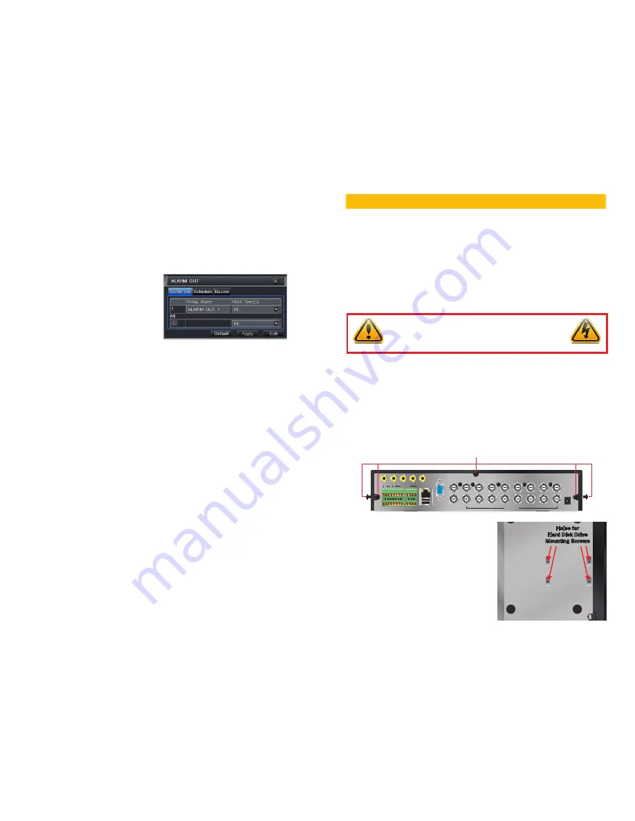
9.1 INSTALLATION/REMOVAL

It is strongly advised against opening the case when atmospheric conditions present the risk 
of static discharge which can damage electronic components.

Whether installing the drive for the first time or removing the old one to install a new one, the 
steps are largely the same:

STEP 1

. Disconnect the DVR from the power source as well as any other connections.

STEP 2

. Remove screws (the number will vary depending on your model) from the side 

and rear of your DVR as indicated in 

Picture 9-1

PICTURE 9-1

PICTURE 9-2

STEP 3

. Remove the case by sliding it 

backwards and then lifting off.

STEP 3A

. If removing a hard drive, you 

will need to unscrew the four drive 
mounting screws at the bottom of the 
DVR or on the internal mounting rack.

Holes for 

Hard Disk Drive

Mounting Screws

Holes for 

Hard Disk Drive

Mounting Screws

WARNING! ELECTRIC SHOCK RISK!

The DVR 

MUST

 be unplugged from all power sources as well as from 

the cameras before opening the case. Failure to do so can result in 
damage to the DVR or its components as well as injury or death.

Summary of Contents for QT SERIES

Page 1: ...1 User Manual Conventional and SDI DVRs QT SERIES...

Page 2: ...es that do not exactly match those on your display This manual was accurate at the time it was completed However because of our ongoing effort to constantly improve our products features and functions...

Page 3: ...ideo Output 60 Live Viewing 60 Recording 60 3 4 Quick Playback 61 4 MAIN MENU SETUP 64 4 1 Basic Configuration 64 Menu Navigation 64 Setup 64 4 2 Live Configuration 67 4 3 Record Configuration 69 4 4...

Page 4: ...nd contact Q See immediately n Keep product surfaces clean and dry To clean the outside case of the DVR gently wipe using a lightly dampened cloth only use water do not use solvents n Do not operate t...

Page 5: ...remote playback in Network Client through LAN or internet Supports recording in CIF and D1 resolutions SDI models support recording in 720P and 1080P HD resolutions ALARM 1 4 channel alarm output and...

Page 6: ...ions in menus 4 ENTER Confirm Selection 5 INDICATOR LIGHTS Shows status of the DVR Functions and the Hard Drive 6 MENU Opens the Main Menu Increases the value in Setup mode 7 USB PORT Used for externa...

Page 7: ...GHT Shows power status of the DVR 9 INFRARED WINDOW Receives signals from the remote control 10 BACKUP Enter Backup mode Decreases the value in Setup mode 11 USB PORT Used for external USB backup devi...

Page 8: ...input 2 VIDEO IN Video input from up to 4 cameras 3 VIDEO OUT BNC connector for TV or monitor 4 VGA PORT VGA output for 19 or larger monitor 5 POWER SWITCH Use to turn on the DVR as well as to turn of...

Page 9: ...lection 11 DIRECTION MULTISCREEN 1 Navigate through on screen options 2 Change screen display mode between 1 4 9 and 16 channels 12 USB USB port to connect USB flash or external hard drives to update...

Page 10: ...ate through on screen options 2 Change screen display mode between 1 4 and 9 channels 11 ENTER Confirm selection 12 USB USB port to connect USB flash or external hard drives to update firmware or back...

Page 11: ...Outer ring navigates through menus Inner knob increases or decreases speed of fast forward or rewind 3 5 7 4 1 2 6 9 8 10 11 12 14 16 13 17 15 16 BACK PANEL 1 2 4 6 9 8 7 10 11 14 12 17 16 15 13 18 5...

Page 12: ...TROL KNOB Outer ring navigates through menus Inner knob increases or decreases speed of fast forward or rewind 3 5 7 4 1 2 6 9 8 10 11 12 14 16 13 17 15 16 BACK PANEL ITEM NAME FUNCTION 1 VIDEO OUT BN...

Page 13: ...13 USB USB port to connect USB flash or external hard drives to update firmware or back up recordings ITEM NAME FUNCTION 1 POWER SWITCH Use to turn on the DVR as well as to turn off after powering do...

Page 14: ...selections in menus 11 RETURN Confirms selection 12 USB PORT Used for external USB backup devices ITEM NAME FUNCTION 1 VIDEO OUT BNC connector for TV or monitor 2 SPOT OUT Connect to another monitor...

Page 15: ...ays system information 11 BACKUP Enter Backup mode Decreases the value in Setup mode 12 AUDIO Mutes or unmutes audio 13 PTZ Enter PTZ mode ITEM NAME FUNCTION 1 PTZ Connections for Pan Tilt Zoom speed...

Page 16: ...OOM Enter Search mode Controls Zoom function in PTZ mode 10 INFO Displays system information 11 BACKUP Enter Backup mode Decreases the value in Setup mode 12 AUDIO Mutes or unmutes audio 13 PTZ Enter...

Page 17: ...CONTROL KNOB Outer ring navigates through menus Inner knob increases or decreases speed of fast forward or rewind ITEM NAME FUNCTION 1 VIDEO OUT BNC connector for TV or monitor 2 HDMI HDMI video outp...

Page 18: ...k FF Fast Forward STOP Quits Playback mode Also switches video output mode 17 CONTROL KNOB Outer ring navigates through menus Inner knob increases or decreases speed of fast forward or rewind 3 5 7 4...

Page 19: ...vigates through menus Inner knob increases or decreases speed of fast forward or rewind 3 5 7 4 1 2 6 9 8 10 11 12 14 16 13 17 15 16 BACK PANEL ITEM NAME FUNCTION 1 VIDEO OUT BNC connector for TV or m...

Page 20: ...de 13 USB USB port to connect USB flash or external hard drives to update firmware or back up recordings ITEM NAME FUNCTION 1 POWER SWITCH Use to turn on the DVR as well as to turn off after powering...

Page 21: ...up mode in LIVE VIEW 11 MENU Increase the value in SETUP Enter menu in LIVE VIEW 12 SEARCH Enters Search Mode 13 USB USB port to connect USB flash or external hard drives to update firmware or back up...

Page 22: ...or status Also switches video output mode 7 SEARCH ZOOM Enter Search mode Controls Zoom function in PTZ mode 8 INDICATOR LIGHT Shows power status of the DVR 9 INFRARED WINDOW Receives signals from th...

Page 23: ...face or status Also switches video output mode 7 SEARCH ZOOM Enter Search mode Controls Zoom function in PTZ mode 8 INDICATOR LIGHT Shows power status of the DVR 9 INFRARED WINDOW Receives signals fro...

Page 24: ...re or back up recordings ITEM NAME FUNCTION 1 PTZ ALARM INTERFACE Connections for Pan Tilt Zoom speed dome cameras Y Z Input ports for 4 alarms One output port for external alarm 2 HDMI HDMI video out...

Page 25: ...PICTURE 2 2 PICTURE 2 3 1 2 3 4 5 10 11 6 7 8 9 12 13 14 15 Item Button Function 1 POWER Soft power down switch Use this before unplugging the DVR 2 INFO Get information about the DVR such as HDD spa...

Page 26: ...Main menu 13 Exit Exits menu or interface 14 PTZ Controls Controls PTZ camera including zoom focus iris and speed 15 Preset Opens PTZ preset settings 16 Cruise Opens PTZ cruise settings 17 Light Turns...

Page 27: ...arked VGA on the back of the DVR STEP 2 Plug the other end of the VGA cable into the similar port on the back of the monitor STEP 3 Plug the monitor s power cable into the surge protector High Definit...

Page 28: ...d for the main display This extra display will mirror whatever is shown on the primary display but it will not show the menu or cursor It is not possible to divide channels across two displays Loop Ou...

Page 29: ...c Configuration STEP 4 The Login screen will appear Enter the User Name and Password admin and 123456 respectively using the Virtual Keyboard described in the last chapter Click ENTER on the keyboard...

Page 30: ...RE 3 4 PICTURE 3 5 You can move camera views to a new position by clicking and dragging the desired channel s display When a channel s view is dragged into another area the view that it replaces will...

Page 31: ...s but each user s situation will be different and directions for adjusting these settings can be found in Section 4 3 Record Configuration PICTURE 3 9 PICTURE 3 10 3 4 QUICK PLAYBACK Pushing the playb...

Page 32: ...you to save a segment of the video record rather than having to back up the entire file To select a segment move the Playback Progress Bar to before the desired location in the video and begin playba...

Page 33: ...s No Image When Logout Device Name Device ID Video Format Password Check Show System Time Max Online Users Video Output Language Logout After Minutes No Image When Logout EDVR 0 NTSC 10 VGA 1280x1024...

Page 34: ...time before making changes in other menus Most of the options within this menu are self explanatory If you are unsure of your time zone the date and time settings on your computer or searching online...

Page 35: ...lution fps Encode Quality Max Bitrate 1 2 3 4 All All Remaining 0 CIF 0 D1 Remaining 0 CIF 0 D1 30 30 30 30 30 30 30 30 CBR CBR CBR CBR CBR CBR CBR CBR Higher Higher Higher Higher Higher Higher Higher...

Page 36: ...r ID and date stamp and where it ll appear on the screen Drag and drop the location of the camera name and date time stamp to your desired location on the screen This can be done individually or globa...

Page 37: ...ter is powered on before proceeding This window displays the information on the DVR s local network and Internet addresses which will allow you to access the DVR on a network As discussed in the Remot...

Page 38: ...how your DVR will send out e mail alerts You will be able to send e mail alerts to three addresses NOTE Depending upon your settings the system can generate a lot of e mail alerts For that reason we r...

Page 39: ...date Hours UPnP Email Email Other Settings Other Settings MyQ See com myname myemailaddress com myqseeaccountpassword myaccount myq see com 3 MyQ See com myname myemailaddress com myqseeaccountpasswor...

Page 40: ...etrieved from mobile or external storage devices and recorded onto the DVR PICTURE 4 31 4 8 FILE SEARCH PLAYBACK AND MANAGEMENT Access the recordings on the DVR play them back and backup the recording...

Page 41: ...e event file you wish to play back 2 3 4 1 6 7 8 5 SEARCH Search Time Search Image Event Search File Management Search Delete Delete Lock Lock Save Save Save All Save All Time Search Image Event Searc...

Page 42: ...ill create a standard avi file usable by most media playback software If you choose the DVR format you need to select the Desktop Player option see Picture 5 2 as well This will save a stand alone pla...

Page 43: ...MCU MicroController Unit kernel if applicable and firmware versions can be found here along with the device s name and ID EVENT INFORMATION This window lists recorded events This list can be searched...

Page 44: ...e 1 D1 30 2 D1 30 3 D1 30 4 D1 30 5 D1 30 6 D1 30 7 CIF 30 8 CIF 30 Disk ID Status Disk ID Status 1 1 19 19 PICTURE 6 9 PICTURE 6 10 6 3 DISK MANAGEMENT This window displays information on the drive o...

Page 45: ...rade process will restore factory defaults Other models will retain their user settings NOTE While a Macintosh computer can read and write to a drive in the FAT32 format it cannot reformat a USB flash...

Page 46: ...from this window in the Serial Port and Advanced tabs Serial Port Serial Port Advanced Advanced P T Z P T Z Default Default Apply Apply Exit Exit CH Enable Address Baud Rate Protocol Simulative Cruis...

Page 47: ...009 preset010 preset010 PRESET Channel 1 PRESET Channel 1 Setting Setting Setting Setting Setting Setting Setting Setting Setting Setting Setting Setting Setting Setting Setting Setting Setting Settin...

Page 48: ...ounded 2 A grounding signal is required for the alarm input 3 When connecting the DVR to another device including another DVR through the alarm input a relay should be used to separate them Parameter...

Page 49: ...rs such as infrared motion detectors or contact alarms which are connected to it There are five submenus Sensor Motion Video Loss Other and Alarm Out SENSOR In this window you can setup optional exter...

Page 50: ...ly Click and drag with the mouse on the screen to draw or erase the grid in select areas Sensitivity 6 Sensitivity 6 As sensitivity is influenced by color and light level you can adjust its values acc...

Page 51: ...noted that while this is the only user serviceable part within the case besides the battery and you will not void your warranty by installing or upgrading your hard disk drive care must be taken to a...

Page 52: ...SOLUTION FRAME RATE FPS VIDEO QUALITY BIT RATE bps SPACE USED MB h NTSC PAL CIF 30 25 Highest 1000k 465 Higher 768k 297 Medium 512k 230 Lower 256k 115 Lowest 128k 56 D1 30 25 Highest 2M 912 Higher 1 5...

Page 53: ...th the system Please try another mouse 7 What can I do when the DVR starts and displays please wait all the time a First possible reason hard drive power cable and or data cable are not securely conne...

Page 54: ...TIONS Parameter QT454 QT426 QT428 COMPRESSION Compression Format Standard H 264 Baseline VIDEO Video In Composite 1 0V p p 75 BNC x 4 Composite 1 0V p p 75 BNC x 16 Composite 1 0V p p 75 BNC x 8 Video...

Page 55: ...o 2TB each OTHER INFO Voltage 12V3A 110 220 Optimal Temperature 50 F to 104 F 10 C to 40 C 10 to 90 Humidity Power Consumption 10W 22W 42W Parameter QT4532 QT4516 QT2124 COMPRESSION Compression Format...

Page 56: ...MPRESSION Compression Format Standard H 264 Baseline VIDEO Video In Composite 1 0V p p 75 BNC x 8 Composite 1 0V p p 75 BNC x 16 Composite 1 0V p p 75 BNC x 16 Video Out COMPOSITE 1 0V p p 75 BNC x 2...

Page 57: ...R INFO Voltage 12V3A 12V5A Optimal Temperature 50 F to 104 F 10 C to 40 C 10 to 90 Humidity Power Consumption 20W 10W without hard drive Parameter QT5140 QT5680 QT4760 COMPRESSION Compression Format S...

Page 58: ...ure that all camera and other cable connections on the back of the DVR are secure before bolting the brackets to the rack Q See is proud to back all of our products with a conditional service warranty...

Page 59: ...S OR COMMENTS CONTACT US PRODUCT SUPPORT DOWNLOADS FIRMWARE UPDATES MANUALS 24 7 Technical Resources Live Chat M F 9 5 PST www Q See com Support Digital Peripheral Solutions Inc 8015 E Crystal Drive A...

Reviews: