


64
65
4.1 BASIC CONFIGURATION
This chapter is intended to help you get your DVR up and running before you activate any
advanced features which are covered in later chapters. You can use the mouse, remote
control and the buttons on the front of the DVR to operate your system, but for convenience,
we will be discussing operations using the mouse. Information on P.T.Z. cameras and alarms
will be found in their own chapters,
Chapters 7
and
8
, respectively.
MENU NAVIGATION
Navigation through the user interface is point and click. Double-clicking on an icon within a
given menu will open that menu, or a submenu. The Main Menu is the starting point to reach
all of the DVR’s settings and features. Selecting the
Menu
icon on the left of the
Control Bar
or pressing the
Menu
button on the DVR and remote control open the
Main Menu
.
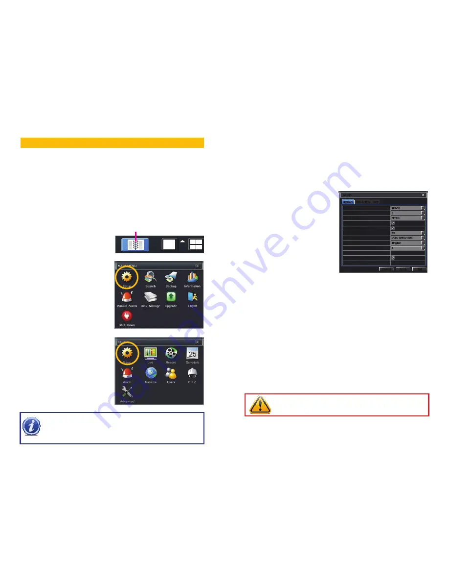
MAIN MENU SETUP
CHAPTER 4
PICTURE 4-2
PICTURE 4-1
Clicking on any icon will open the relevant
menu.
SETUP
From the
Setup
menu select the
Basic
menu
by clicking on its icon.
PICTURE 4-3
Main Menu
NOTE!
When configuring your settings, you will always need to click
Apply
to save your
current settings before closing the window with
Exit
otherwise your changes will be lost.
You may click
Exit
or the close window box (
X
) in the upper right of the window to close
without saving changes but an alert will pop up asking if you wish to save changes. Click
OK
to save changes or
Cancel
to continue without saving. You may select the
Default
button to restore your settings to those set at the factory.
System
System
Date & Time
Date & Time
DST
DST
BASIC
BASIC
Default
Default
Apply
Apply
Exit
Exit
Device Name
Device ID
Video Format
Password Check
Show System Time
Max Online Users
Video Output
Language
Logout After [Minutes]
No Image When Logout
Device Name
Device ID
Video Format
Password Check
Show System Time
Max Online Users
Video Output
Language
Logout After [Minutes]
No Image When Logout
EDVR
0
NTSC
10
VGA 1280x1024
English
5
EDVR
0
NTSC
10
VGA 1280x1024
English
5
PICTURE 4-4
BASIC MENU
There are three tabs covering
System
,
Date & Time
and
Daylight Savings Time
(DST). In
the first tab, System you will set the date, time along with other desired settings.
System Tab
The following settings can be changed in this menu:
Device Name:
This will display when you
access the DVR remotely via your
mobile device, a web browser or
through the CMS software. Naming
the device will help users recognize
the device when monitoring
numerous DVRs remotely.
Device ID:
If you have multiple systems, you
can give this device a numerical ID.
Video Format:
Select between NTSC (North
America) or PAL (Europe) video
standards.
Password Check:
By enabling this, a
user will need to enter name
and password when performing
configuration operations.
Show Time:
Displays the time on-screen in Live View.
Max Network Users:
Set the maximum number of network connections - up to 10.
VGA Output:
Chose the configuration that best fits your monitor. Options are: VGA800*600,
VGA1024*768 (Default), VGA1280x1024 and CVBS. NOTE: VGA is for VGA monitors
while CVBS is for TV monitors connected using a BNC/RCA adaptor. Switching
between VGA and CVBS will change the menu output mode. Please be sure to have
the correct monitor on hand when changing output mode.
Language:
Select your preferred menu language. The DVR will have to restart for this change
to take effect.
Logout After... :
You can have the DVR automatically log a user out after a period of inactivity.
The period can range from 30 seconds (.5), 1, 3 or 5 minutes or never.
No Image When Logout:
The monitor will not display the Live View when this box is
unchecked.
IMPORTANT!
After changing the Language or Video Format, the device will
need to be restarted.


