background image

Q-SEE QUICK INSTALLATION GUIDE 

M

M

O

O

D

D

E

E

L

L


N

N

U

U

M

M

B

B

E

E

R

R


Q

Q

S

S

D

D

R

R

1

1

6

6

8

8

G

G

R

R

T

T

C

C

/

/

B

B


2 | P a g e  

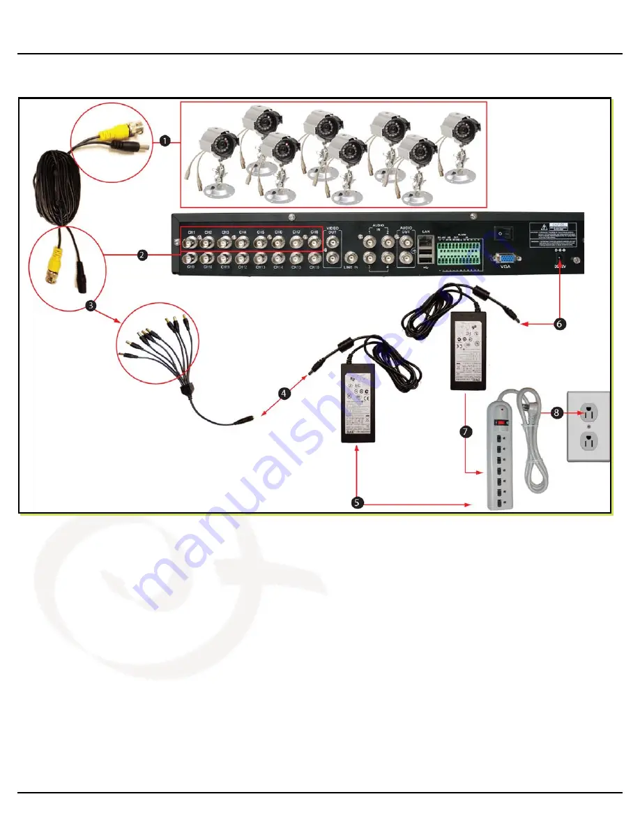
PART 2 - DVR CAMERA AND POWER CONNECTIONS 


(Figure 1)  


1.  Connect one end of the 60 Ft. extension cables to the cables that are connected to the cameras (not 

shown). 

2.  Connect the other end of the 60 Ft. extension cable to the DVR as illustrated in Figure 1.  
3.  Following the illustration in Figure 1, plug the power connecter of the 60 Ft. extension cable to the 8 

way splitter.  Repeat steps 1 through 3 for each camera.  

4.  Plug the end of the camera power adapter into the 8 way splitter.  
5.  Plug the power adapter into the surge protector.  Repeat steps 1-4 until all cameras are connected to 

a power adapter.  

6.  Plug the power adapter for the DVR into the back of the DVR as illustrated in Figure 1.   
7.  Plug the power chord of the power adapter into the surge protector.  
8.  Plug the surge protector in to an electricity outlet.   


Please note that it is STRONGLY recommended to use a surge protector that is UL-1449 rated.  
Look for a clamping voltage of 330 or lower, a Joule rating of at least 400 and a response time of 
10 nanoseconds or less.   

Summary of Contents for QSDR16RTC/B

Page 1: ...Quick Installation Guide 16 Channel H 264 Compression DVR with CIF Real Time Recording and 8 Color CCD Camera Kits M MO OD DE EL L Q QS SD DR R1 16 68 8G GR RT TC C B B...

Page 2: ...ntrol USB 2 0 Mouse Ethernet Cable BNC M RCA F Adapters 2 Included Camera Cables 8 Included Power Supply 8 Way Splitter For Cameras Pre Installed Hard Drive 8 Cameras with Stands 4 QD28414 Cameras 6mm...

Page 3: ...way splitter Repeat steps 1 through 3 for each camera 4 Plug the end of the camera power adapter into the 8 way splitter 5 Plug the power adapter into the surge protector Repeat steps 1 4 until all ca...

Page 4: ...end of the RCA not included cable to the Video Input on the TV if you are using a television screen 3 If you are using a PC monitor plug the VGA cable not included to the VGA port on the DVR 4 Connec...

Page 5: ...r remote control The Main Menu offers the following Setup Features CAMERA Setup name display position image view and record quality of each channel cameras RECORD Enable recording audio set resolution...

Page 6: ...reboot the DVR You can also click on the DEFAULT button to use the system defaults The system default settings are Hr 01 00 am 07 59 am No recording Hr 08 00 am 18 59 pm General recording Time Schedul...

Page 7: ...put a specific date and click Search you will find all the recordings for that day When you select an item you will playback the recordings in 4 channel mode or click File list button to display File...

Page 8: ...sh to back up by placing a check mark in the accompanying green box and hit the BACKUP button on the right of the screen You will then receive a pop up screen as illustrated in Picture 22 showing you...

Page 9: ...or Comments Contact Us Mailing Address Customer Service DPS Inc Phone 877 998 3440 x 538 8015 E Crystal Dr Email cs dpsi usa com Anaheim CA 92807 Live Chat from our Website Website Tech Support http...

Reviews: