


8
H/W SENSOR SETUP
CHANNEL-1 TYPE:NORMAL-OPEN
CHANNEL-2 NOT INSTALLED
CHANNEL-3 NOT INSTALLED
CHANNEL-4 NOT INSTALLED
CHANNEL-5 NOT INSTALLED
CHANNEL-6 NOT INSTALLED
CHANNEL-7 NOT INSTALLED
CHANNEL-8 NOT INSTALLED
CHANNEL-9 NOT INSTALLED
( ) MOVE
(
SEL
)
SELECT (MENU)EXIT
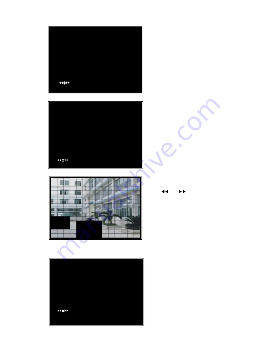
Area Selection:
The picture from a camera is divided into blocks, press
[▲
,
▼
,
and
] buttons to select a block, and
press [
SEL
] button to set the block to be active or not.
When the block is transparent, it’s active for motion
detection recording; when the block is covered by
shadow, it is not active for motion detection record.
Press
“stop”
button to disable all areas, press
“All”
button to enable all areas
5.7 Hard Drive Setup
(1) OVERWRITE ENABLED: If you choose YES
(default setting), recording continues and overwrites
previous recordings when hard drive space is Full. If
you choose NO, the recording session stops when the
hard drive capacity is full.
(2) MASTER HDD SIZE
:
This shows the size of the
primary hard drive installed in the DVR.
(3) MASTER HDD USED: It shows the space used
on the first hard disk drive for recording.
(4) MASTER HDD FORMAT
:
If you format the
CH5 ON LEVEL 2 AREA
CH6 ON LEVEL 2 AREA
CH7 ON LEVEL 2 AREA
CH8 ON LEVEL 2 AREA
CH9 ON LEVEL 2 AREA
HARDWARE SENSOR SETUP: This is the sub
menu for setting up external motion sensor devices.
There are 3 different modes for sensor setting: NOT
INSTALLED, NORMAL-CLOSE and NORMAL-OPEN.
It depends on what type of external sensor you are using. If
sensor’s output is NORMAL-OPEN, then select
NORMAL-OPEN mode in DVR.
MOTION DETECTOR SETUP:
ON/OFF: Enable or disable motion detection recording.
LEVEL
:
Sensitivity for motion detection. There are 3 levels of
sensitivity: Level 1, 2 and 3. Level 3 is the highest sensitivity
level.
AREA
:
Select motion detection active area.
[Note] You do not need to install any external sensors if you
want to use the DVR’s internal motion sensor capability.
MOTION DETECTOR SETUP
CH1 ON LEVEL2 AREA
CH2 ON LEVEL2 AREA
CH3 ON LEVEL2 AREA
CH4 ON LEVEL2 AREA
CH5 ON LEVEL2 AREA
CH6 ON LEVEL2 AREA
CH7 ON LEVEL2 AREA
CH8 ON LEVEL2 AREA
CH9 ON LEVEL2 AREA
( ) MOVE
(
SEL
)
SELECT (MENU)EXIT
HARD DRIVE SETUP
O
VERWRITE ENABLED [ ON]
ST3160215A
MASTER HDD SIZE 160133MB
MASTER HDD SIZE 124931MB 78%
MASTER HDD FORMAT
SLAVE HDD SIZE N/A
SLAVE HDD USED N/A
SLAVE HDD FORMAT
( ) MOVE
(
SEL
)
SELECT (MENU) EXIT


