Q-See QSD6209C9--250 User Manual Download Page 19

18 

[

N-REC

]: indicates the current record schedule is set as NO-RECORD mode. 

[

39%

]: indicates the percentage of hard drive space currently used.  

[M]: HDD info ([M] Master Hard Disk; [S] Slave Hard Disk) 


6.2Audio Recording  

      [

]: indicates this video channel is bundled with an audio port, and the audio input is on.  

[ ]: indicates the audio input is off. 

[

]: indicates the audio is being recorded and the audio input is on. 

    You can press


the [MUTE] button on the front panel to mute the audio output. The audio input 

can be still recorded while the output is muted. Press the [MUTE] button again to preview the 

audio. 

If  you  press  the

REC

button  the  DVR  goes  into  REC  mode.  The  DVR  will  continue  

recording based on the set ‘Record Schedule’. In record mode you can change channel view and 

switch the audio channel. However you can not playback while in record mode. 


6.3 Stop Recording 

Press the [

] stop button and the DVR will stop recording. If the password protection function is 

enabled the system will prompt you to input password. Only the correct password can stop the 

recording process. 


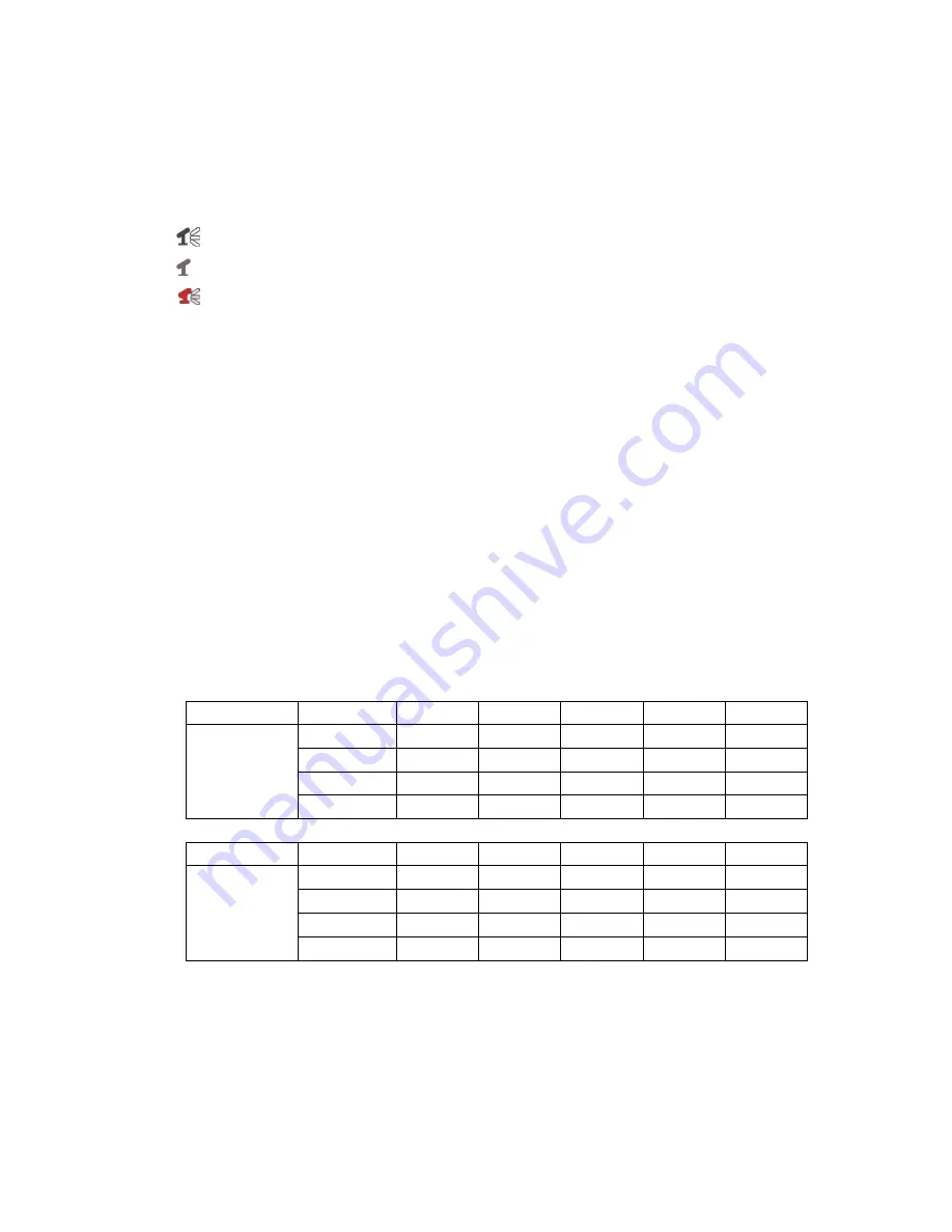
6.4 Estimated Recording Length 

Estimated record time based on 160GB HDD using 9 cameras in Hours 
                                                                                                                         

Standard 

Quality 

60fps 

48fps 

32fps 

16fps 

1fps 

NTSC 

Highest 

27 

34 

51 

103 

1653 

High 

39 

49 

73 

146 

2346 

Normal 

47 

59 

89 

178 

2853 

Lower 

53 

66 

100 

200 

3200 


Standard 

Quality 

50fps 

36fps 

24fps 

12fps 

1fps 

PAL 

Highest 

28 

39 

59 

118 

1422 

High 

40 

55 

83 

166 

2000 

Normal 

49 

68 

102 

203 

2444 

Lower 

54 

76 

114 

228 

2733 


Summary of Contents for QSD6209C9--250

Page 1: ......

Page 2: ...ule 7 5 6 Sensor Setup 7 5 7 Hard Drive Setup 8 5 8 Miscellaneous Setup 9 5 8 1 Password Change 9 5 8 2 Set Time 10 5 8 3 Hidden Channel 10 5 8 4 Audio port setup 10 5 8 5 PTZ Setup 11 5 8 6 Image Par...

Page 3: ...s 500GB SATA Hard Drive l Supports USB backup and playback by PC l Supports PTZ Control via RS485 Port l Supports Remote Control l Supports Fixed Hard Drive l Supports VGA Output Chapter 2 Hardware La...

Page 4: ...16 RS485 Sensor Alarm 17 DC Power Input Jack 18 USB Port 2 3 Remote Control 1 9 Select or enlarge Channel 1 9 0 Number ALL Display All Channels Menu Enter or exit setup menu Move up left cursor Move d...

Page 5: ...inputs and 1 monitor output BNC connectors 3 2 VGA Output There is 1 CRT or LCD monitor output with VGA connector Chapter 4 DVR System Boot 4 DVR System Boot 4 1 Display DVR Firmware Version 4 2 Dete...

Page 6: ...not be able to record to the HDD Press SEL to format or press MENU to cancel While the DVR is running the monitor will display the view from the cameras as follows Bottom right System Date and Time Bo...

Page 7: ...the sum of the frame rate you select for all cameras is more than 50fps PAL 60fps NTSC the DVR will automatically adjust the largest frame rate value to a smaller value Press and buttons to select a c...

Page 8: ...em will record when sensor is triggered NOTE You must press the REC button to record in these three modes 5 6 Sensor Setup Note Sensors and extension alarms do not come with the DVR system you need to...

Page 9: ...st hard disk drive for recording 4 MASTER HDD FORMAT If you format the CH5 ON LEVEL 2 AREA CH6 ON LEVEL 2 AREA CH7 ON LEVEL 2 AREA CH8 ON LEVEL 2 AREA CH9 ON LEVEL 2 AREA HARDWARE SENSOR SETUP This is...

Page 10: ...correct password the following message will flash 3 times password correct Hard Disk Formatting Otherwise the following error message will be displayed on the screen Password Incorrect Note The Facto...

Page 11: ...record on the channel 5 8 4 Audio port setup When you move the cursor to AUDIO PORT RECORD and push the SELECT button the option will be changed to OFF or ON If the option is ON the audio will be reco...

Page 12: ...the camera 1 4 ID set 1 32 5 8 6 Image Parameters CON press left or right button of remote control to set image contrast value BRI press left or right button of remote control to set image brightness...

Page 13: ...ile two DVR s are in your local network and the first code 00 must not be changed IPALLOCATION The DVR supports DHCP and Static IP modes If using DHCP Dynamic Host Configure Protocol mode you must hav...

Page 14: ...y is usually housed at the ISP The gateway address is provided by your ISP If you have the DVR attached to a router then the router s address will be the gateway NETWORK SETUP MAC ADDRESS IP ALLOCATIO...

Page 15: ...be only allowed to view the live pictures NETWORK SETUP MAC ADDRESS IP ALLOCATION IP ADDRESS SUBNET MASK GATEWAY DNS1 ADDRESS DNS2 ADDRESS HTTP PORT USER SETUP DDNS SETUP HTTP PORT 80 1024 49151 MOVE...

Page 16: ...main name instead of a dynamic address After registration you will have a username and password You can also register your domain name on the website Please refer to Chapter 5 P Network Setup for more...

Page 17: ...on then select the Pop up Blocker option and select Turn Off Pop up Blocker You will also need to enable Active X controls To do so go to the Internet Explorer tool bar and select the tools option the...

Page 18: ...nformation below on the screen the red dot next to the channel name indicates that the channel is being recorded A REC indicates the current record schedule is set as NORMAL RECORD mode S REC indicate...

Page 19: ...REC mode The DVR will continue recording based on the set Record Schedule In record mode you can change channel view and switch the audio channel However you can not playback while in record mode 6 3...

Page 20: ...the arrow is pointing at a specific event the date and time below HARD DRIVE MASTER shows the beginning date and time to the ending date and time of that recorded event To manually input a specific ti...

Page 21: ...PCVIEWER EXE 3 Follow the prompts on your PC to finish the installation 8 2 Program Interface System will detect the HDD automatically when you connect the USB cable to your PC An USB icon will appear...

Page 22: ...ode 16 Play 6 Event List 17 fast forward 7 Control Panel 18 forward one frame 8 Remote DVR Control 19 Playback Slider 9 Change Storage Device 20 Audio Slider 10 Capture Image 21 Software Version 11 Ba...

Page 23: ...22 Press button 7 to configure the program s local settings Press button 16 to play video...

Page 24: ...igh Normal low Audio ADPCM2 CODEC Video MPEG4 Motion Detection Settable Window Level Microprocessor 32 bit RISC Processor Network Interface TCP IP RJ45 Network Monitor IE Internet Explorer PC Viewer S...

Page 25: ...24 Appendix Appendix 1 System connect sketch map 2 Accessories Included With DVR Combo...

Page 26: ...per power environment temperature humidity and lightening strike etc that cause equipment damage 3 Damage caused by acts of nature earthquake and fire etc 4 Equipment damage caused by the maintenance...

Page 27: ...ny means without our company s prior written permission 1 Our products are under continual improvement and we reserve the right to make changes without notice so no guarantee is given as to the correc...

Reviews: