


PART 3 - CONNECTING THE DVR TO YOUR DISPLAY
VGA
AUDIO/VIDEO
USB
HDMI
RS232
NET
DC 19V
NO
C
1
NO
C
2
1
2
3
4
5
6
7
8
A
B
CNTRL
12V
1
2
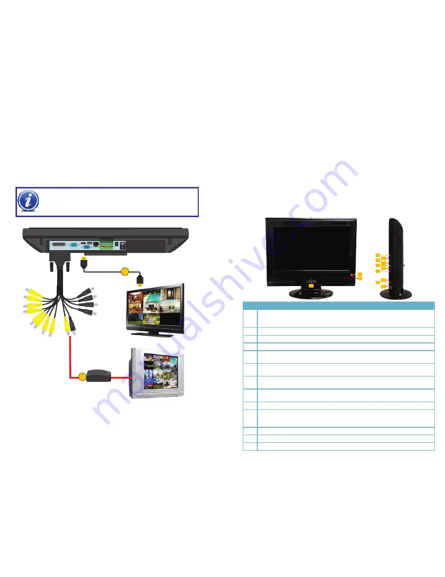
NOTE!
You may use both the built-in monitor and any connected
display simultaneously with this DVR. The image on the displays will be
identical to that on the built-in screen.
1. To Connect to an HDMI display:
Connect the DVR to a high definition display using an HDMI cable (not included).
2. To Connect to a VGA Monitor:
You will need to purchase a BNC to VGA converter box (depending on model, you may
also need a BNC(F) to BNC(F) cable). Connect the converter to the Video Out plug on
the dongle and then to a monitor using a VGA cable.
This DVR can be controlled through the USB mouse or by using the the remote control. We
have found that the majority of our customers prefer to operate their DVRs using the USB mouse
because of its ease of use and flexibility and our manual is set up with this in mind. The remote
control allows you to perform most of the day-to-day functions from a convenient distance. It
functions as a typical remote control with additional buttons allowing you to navigate through
menus and control functions. We recommend that you configure your DVR using the mouse
controls, reserving the remote control for operations such as live viewing, file search and playback.
PART 4 - DVR CONTROLS
FRONT AND SIDE PANELS
In addition to the ports located on the underside of the DVR, there are eight buttons and three
ports on the front and side panels. A single button on the front panel is used to turn the DVR or its
monitor on or off. The seven buttons on the side have multiple functions depending on context.
Additionally, there are ports for a headphone, microphone and for a USB flash drive.
Using the DVR as a Computer Monitor
The DVR’s LCD screen can be used as a computer monitor by plugging in a VGA monitor cable
from a computer into the VGA In port (located between the dongle and HDMI ports) on the back of
the system as you would with any regular computer monitor. This can be useful in the short term
when setting up network access of the DVR, or it can be a long-term solution such as saving space
or to hide the purpose of the DVR. You will not be able to use the screen to view input from the
computer and the cameras at the same time. External video input from a computer will override the
DVR’s video. You will need to install a monitor switch box between the computer and the DVR to
manually “turn off” the computer’s video feed, allowing the system to display normally.
2
1
4
5
6
7
8
9
10
11
12
13
3
#
Function
1
When the device is off, press it for several seconds to boot up the device. Press it for a
short time to turn off screen.
When the device is on, press and hold to shut down the device.
2
Power indication light
3
Infrared remote control signal receiver
4
Mode button. Used to switch between PC input signal and main board signal.
5
Switch the current activated control. Go upward when used to modify setup.
Auxiliary function such as control and switch the PTZ menu.
6
Switch the current activated control. Go downward when used to modify setup.
Auxiliary function such as control and switch the PTZ menu.
7
Switch the current activated control.
Used to adjust playback control bar to go left during playback.
8
Switch the current activated control.
Used to adjust the playback control bar to go right during playback.
9
Go back to the previous menu or cancel current selection.
10
Confirm current operation
Go to the default button
Go to the menu
11
Headphone/Speaker port
12
Microphone port
13
USB port


