14
15
MOTION DETECTION
Unlike most security cameras, your camera is capable of detecting motion by itself. If you are connecting your camera to a Q-See
security DVR, you will not need to enable this feature as the DVR itself has motion detection capabilities. Enabling motion detection on
the camera while connected to a security DVR can produce adverse results by obscuring the recorded video or generating artifacts
which the DVR will interpret as motion causing it to record unnecessarily.
DETECT SENSE
- The camera’s level of sensitivity to motion.
The value range is 0-127.
BLOCK DISP
- If this is turned on, the camera will generate
pixelated blocks to highlight motion within its view. It should be noted
that if you have this enabled while the camera is connected to a
security DVR, the DVR will record the blocks as part of the video and
these cannot be removed from the recording.
MONITOR AREA
- When enabled, you may select up to four
areas where motion will be detected.
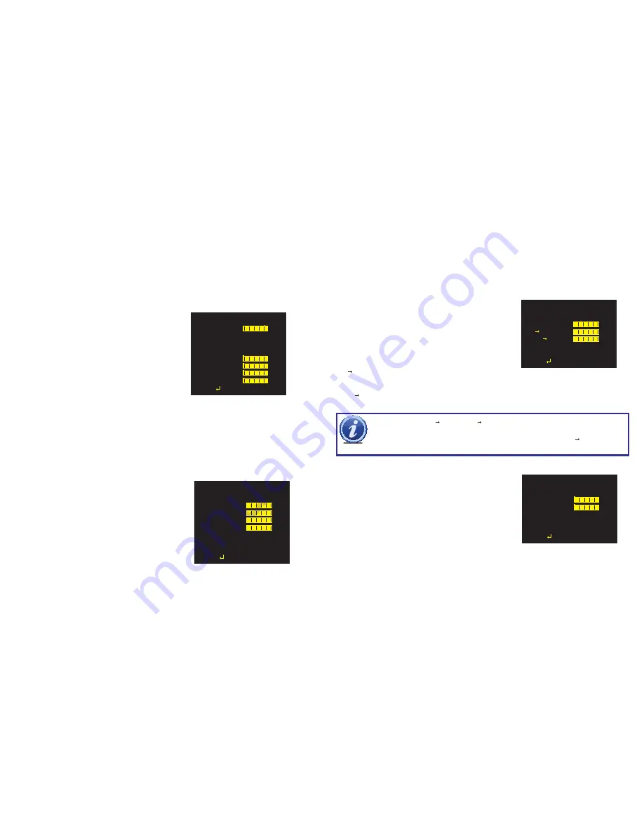
MOTION DETECT
DETECT SENSE 111
BLOCK DISP
OFF
MONITOR AREA OFF
AREA SEL
1/4
TOP
000
BOTTOM
000
LEFT
000
RIGHT
000
RETURN
AREA SEL
- This indicates which of the four motion detection areas you are working on.
TOP, BOTTOM, LEFT, RIGHT
- These settings are used to define the size of the motion detection area.
PRIVACY
This allows you to set up areas within the camera’s view that will be blocked from observation. This may be the location of a
combination lock, keypad or other area that requires privacy. Like Motion Detection above, use of this feature is not recommended
when the camera is connected to a security DVR as it will create artifacts on the video recording which cannot be removed.
AREA SEL
- This indicates which of the eight motion detec-
tion areas you are working on.
TOP, BOTTOM, LEFT, RIGHT
- As in Motion Detection,
these settings are used to define the size of the motion detection
area.
COLOR
- The zone may be set to one of eight colors; red,
green, blue, light green, light blue, light red, white and black.
TRANSPARENCY
- This sets the opacity of the privacy
block.
MOSAIC
- Events occurring in the privacy area are pixelated.
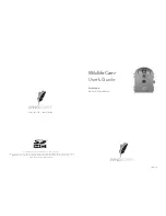
PRIVACY
AREA SEL
1/4
TOP
000
BOTTOM
000
LEFT
000
RIGHT
000
COLOR
1
TRANSP
1.00
MOSAIC
OFF
RETURN
You can adjust the automatic settings.
BURST
- This is a signal sent out by the camera even when no
color information is available. Some DVRs or security video capture
cards may require this to recognize the camera. Q-See security
DVRs do not need a burst signal and it may be turned off.
DELAY CNT
- The time interval delay before switching from day
to night mode.
DAY NIGHT
- Sets the threshold level for when the camera
should switch to night mode.
DAY/NIGHT MODE
This allows you to set the camera to switch automatically from day to night mode (the default) or to permanently set it to Color or B/W
operation. Please note that even when the camera is set to Color mode, it will switch to black and white night vision when there is no
longer enough ambient light to support color video.
NR (NOISE REDUCTION)
In low-light situations, there may be an increase in
“noise” (graininess or random speckles in the video).
Noise reduction can be turned off or set to reduce noise
in the black and white (Y) and/or color (C) portions
of the signal. The value ranges for both the Y and C
filters is 0-15. The higher the value, the more noise is
reduced, but this can reduce image sharpness.
DAY/NIGHT
BURST
ON
DELAY CNT
003
DAY NIGHT
003
NIGHT DAY
003
RETURN
NR
NR MODE
Y/C
Y
004
C
004
RETURN
IMPORTANT!
The DAY NIGHT and NIGHT DAY operations should be tested during installation. Block the lens
for a few seconds to force a switch to night mode. Once the lens is unblocked, the camera should switch back to
day mode in less than 10 seconds. If it does not, slightly increase the threshold in the NIGHT DAY setting. A dimly
lit area or a very low iris setting may also prevent a return to day mode.
NIGHT DAY
- Sets the threshold level for when the camera should switch to day mode.
The value range for both thresholds is 0-255.


