www.qimaging.com
©2016 QImaging. All rights reserved. QI_Retiga R Series Camera_UM_Rev_A5
6
RETIGA R
™
SERIES USER MANUAL
USB 3.0 interface transfers camera settings and image data to the host PC.) The QI Retiga R
Series camera should be connected to a USB 3.0 port. It should also be the only device on its USB
root hub controller (see Figure 2 below). Please see the following section on how to select the
appropriate USB port for optimum camera performance. This ensures the maximum bus bandwidth
is available to the camera for data transfers. USB 3.0 ports are often (but not always) identifiable by
a blue internal socket or the “SuperSpeed” (or just “SS”) USB logo.
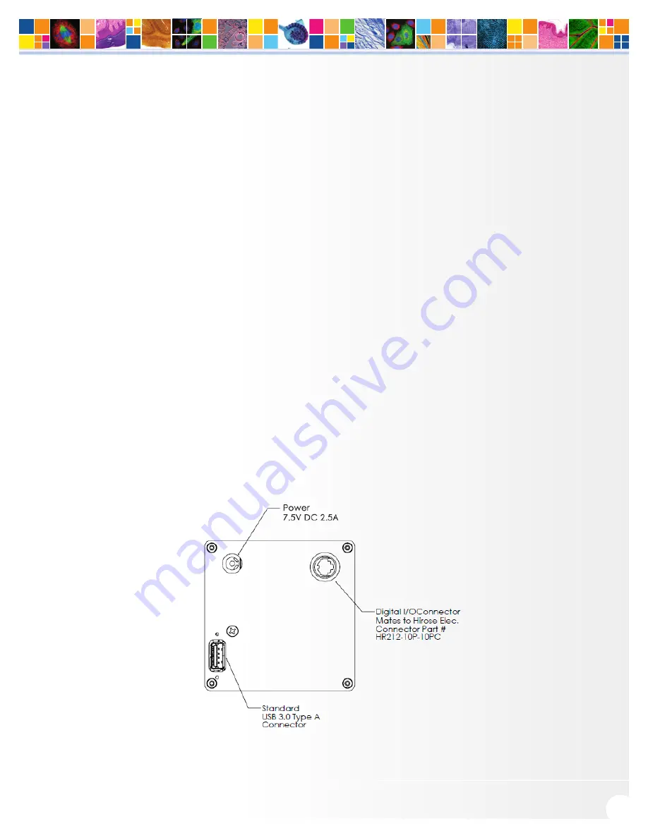
2. After the USB 3.0 cable has been connected to the computer and camera, connect the QI Retiga
R Series camera power supply’s cable to the power connector located on the back of the camera.
(Your Retiga R Series camera is powered by the 12V 5A or greater power supply provided by
QImaging.) Lastly, plug the power supply’s cord into an appropriate power source.
3. Optional: An optional I/O connector is available on your camera for optional hardware triggering.
The I/O connector provides multiple I/O signals that allow highly precise synchronization with
external hardware components such as light sources via TTL signals. Information on how to set up
and configure the Retiga R Series camera for hardware triggering can be found in the next chapter
of this manual.
Note on Selecting the Optimal USB 3.0 Port:
Most modern computers come with both USB 3.0 and USB 2.0 ports. This camera should be connected to a
USB 3.0 port. However, if no USB 3.0 port is available, you can operate the camera with USB 2.0 as well. The
camera is designed to work with USB2.0, at a reduced data rate of 17.5MHz pixels/sec.


