background image

16

17

INSTALLATION AND OPERATION MANUAL SOLAR MODULES Q.PEAK DUO XL-G11.X / BFG – Q CELLS

INSTALLATION AND OPERATION MANUAL SOLAR MODULES Q.PEAK DUO XL-G11.X / BFG – Q CELLS

17

16

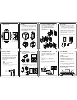
Danger! Risk of fatal injury due to electric 
shock!


Ä

Be sure to maintain the time intervals as 
specified by the inverter manufacturer between 
switching off the inverter and beginning any 
further work.

Danger! Risk of fatal injury due to electric 
shock!


Ä

Never plug or unplug the cable when under 
load. Modules must not carry any current.

1.

 Switch off the inverter.

OFF

EN

4  ELECTRICAL CONNECTION

4.2 ELECTRICAL INSTALLATION SAFETY

2.

 Switch off the DC circuit breaker.

3.

 Measure shutdown in DC String. 

(no DC current flow).

4.

 Disconnect plugs by the use of appropriate 

and qualified tools of the manufacturer.

5.

 When connecting the modules proceed in 

reverse order.

Danger! Risk of fatal injury due to electric 
shock!


Ä

Electrical work may only be performed by 
qualified and skilled personnel (see page 3).


Ä

Ensure correct polarity.


Ä

Use solar cables for the connection at the 
junction box outlet.


Ä

Only interconnect connectors of the same type and 
manufacturer.


Ä

Use minimum 4 mm

2

 copper wires insulated for 

a minimum of 90 °C for field connections.

Note! Module damage may occur!


Ä

Ensure that the cabling is not under mechanical 
stress (Comply with bending radius of ≥ 60 mm).


Ä

Ensure that the cables do not run between module 
and mounting rail or structure (danger of pinch).


Ä

Do not connect modules with different 
orientations or angles of inclination in the same 
string.


Ä

Ensure for a tight connection between the 
plugs. Plugs click together audibly.

EN

click

Danger! Risk of fatal injury due to electric 
shock!


Ä

Ensure that all electrical components are in a 
proper, dry, and safe condition.


Ä

To avoid complex cabling arrangements, it is 
often advantageous to rotate some modules 
180°.


Ä

Module orientation can clearly be identified 
from the front side by the serial number and 
barcode labelled behind the module glass on 
the side with negative connection cable.

EN

Inverter

180°

180°

SOLAR

4  ELECTRICAL CONNECTION

4.3 CONNECTION OF MODULES

Summary of Contents for Q.PEAK DUO XL-G11.X / BFG Series

Page 1: ...INSTALLATION AND OPERATION MANUAL Q PEAK DUO XL G11 X BFG solar module series Valid for Africa Europe LatinAmerica South America...

Page 2: ...ations such as country specific regulations for pressure equipment operational safety hazardous goods and environmental protection Regulations and requirements specific to the system Any applicable la...

Page 3: ...mitrequirements prior to installation of the solar power system Other applicable documents In addition to this Manual following technical information are relevant DOCUMENT TYPE Product data sheet Pack...

Page 4: ...requirements Compliant with local snow and wind loads Properly fastened to the ground the roof or the fa ade Forces acting on the module are relayed to the mounting substructure Ensures sufficient re...

Page 5: ...ast stones rail ends rails with burrs or sharp corners must not be placed near the module backside so as not to touch the laminate under load Ensure that the junction boxes do not touch the mounting s...

Page 6: ...les in the string Parallel Connection Modules may be damaged by the occurrence of reverse currents caused by module defects ground leaks or defective insulation Ensure that the maximum reverse current...

Page 7: ...hown Note Module damage may occur Never step on modules Do not subject modules to any mechanical stress Do not allow any objects to fall onto modules 3 INSTALLATION 3 1 SAFETY AND TRANSPORT Danger Ris...

Page 8: ...t in life threatening injuries The danger increases when several modules are connected in series Please be aware of that the entire open circuit voltage is active even at low levels of solar irradiati...

Page 9: ...skilled personnel see page 3 Ensure correct polarity Use solar cables for the connection at the junction box outlet Only interconnect connectors of the same type and manufacturer Use minimum 4mm2 copp...

Page 10: ...R INSTALLATION Protective Grounding The modules must be grounded in accordance with the local statutory regulations DANGER Risk of fatal injury due to electric shock Do not attempt to fix any problems...

Page 11: ...ace damage may occur Remove snow and ice carefully without force e g with a very soft broom Do not scratch off dirt Module cleaning has to be done by qualified personnel according to the state of the...

Page 12: ...nual solar modules Q PEAK DUO XL G11 X BFG_2022 01_Rev01_AU HANWHA Q CELLS AUSTRALIA PTY LTD Suite 1 Level 1 15 Blue Street North Sydney NSW 2060 Australia TEL 61 0 2 9016 3033 FAX 61 0 2 9016 3032 EM...

Reviews: