SVS-VISTEK
Feature-Set
56
7.1.11
Offset
For physical reasons the output of a sensor will never be zero, even the
camera is placed in total darkness or simply closed. Always there will be
noise or randomly appearing electrons that will be detected as a signal
(dark noise: noise generated without light exposure).
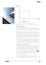
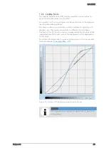
To avoid this dark noise to be interpreted as a valuable signal, an offset
will be set.
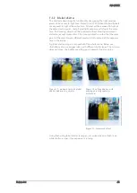
Figure 26: Illustration of dark noise cut off by the offset
Most noise is proportional to temperature. To spare you regulating the
offset every time the temperature changes. A precedent offset is set by the
camera itself. It references certain pixels that never were exposed to light
as black (refer to “
resolution – active and effective
”). So the offset will be
set dynamically and conditioned to external influences.
The offset can be limited by a maximum bit value. If higher values are
needed, try to set a look up table.
In case of multi-tap CCD sensors, offset can be altered for each tap
separately (see tap balancing).
Summary of Contents for EXO Series
Page 21: ...SVS VISTEK Connectors 21 ...
Page 26: ...SVS VISTEK Dimensions 26 Side Right Top ...
Page 27: ...SVS VISTEK Dimensions 27 Bottom Back ...
Page 28: ...SVS VISTEK Dimensions 28 Cross Section 6 2 exo250 CL exo252 CL front side Left ...
Page 29: ...SVS VISTEK Dimensions 29 ...
Page 30: ...SVS VISTEK Dimensions 30 Side Right Top ...
Page 31: ...SVS VISTEK Dimensions 31 Bottom Back Cross Section ...
Page 32: ...SVS VISTEK Dimensions 32 6 3 exo267 CL exo304 CL ...
Page 33: ...SVS VISTEK Dimensions 33 ...
Page 34: ...SVS VISTEK Dimensions 34 ...
Page 35: ...SVS VISTEK Dimensions 35 6 4 exo4000 CL front side Left ...
Page 36: ...SVS VISTEK Dimensions 36 Side Right Top ...
Page 37: ...SVS VISTEK Dimensions 37 Bottom Back ...
Page 38: ...SVS VISTEK Dimensions 38 Cross Section ...
Page 39: ...SVS VISTEK Dimensions 39 6 5 exo5000 U3 front side Left ...
Page 40: ...SVS VISTEK Dimensions 40 Side Right Top ...
Page 41: ...SVS VISTEK Dimensions 41 Bottom Back Cross Section ...
Page 65: ...SVS VISTEK Feature Set 65 ...
Page 71: ...SVS VISTEK Feature Set 71 Figure 42 I O Lines with open end indicate physical in and outputs ...
Page 124: ...SVS VISTEK Troubleshooting 124 Space for further descriptions screenshots and log files ...


