SVS-VISTEK
Getting Started
15
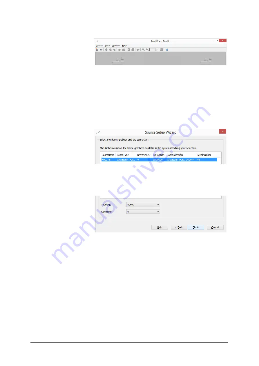
Run Multicam Studio.
>
Add a new “source” to the application
>
Choose “Camera Link industrial Camera…”
>
Click “next”
>
In the list of camera vendors choose
“SVS-VISTEK“ and the camera you want to view.
>
Select frame grabber and connector
>
For “Topology” values refer to the Euresys documentation. At first:
stay with “Mono” for topology.
>
Choose your connector configuration
>
click “Finish”
Now an image should appear, according to your setup configurations
made with ConvCam
Summary of Contents for EXO Series
Page 21: ...SVS VISTEK Connectors 21 ...
Page 26: ...SVS VISTEK Dimensions 26 Side Right Top ...
Page 27: ...SVS VISTEK Dimensions 27 Bottom Back ...
Page 28: ...SVS VISTEK Dimensions 28 Cross Section 6 2 exo250 CL exo252 CL front side Left ...
Page 29: ...SVS VISTEK Dimensions 29 ...
Page 30: ...SVS VISTEK Dimensions 30 Side Right Top ...
Page 31: ...SVS VISTEK Dimensions 31 Bottom Back Cross Section ...
Page 32: ...SVS VISTEK Dimensions 32 6 3 exo267 CL exo304 CL ...
Page 33: ...SVS VISTEK Dimensions 33 ...
Page 34: ...SVS VISTEK Dimensions 34 ...
Page 35: ...SVS VISTEK Dimensions 35 6 4 exo4000 CL front side Left ...
Page 36: ...SVS VISTEK Dimensions 36 Side Right Top ...
Page 37: ...SVS VISTEK Dimensions 37 Bottom Back ...
Page 38: ...SVS VISTEK Dimensions 38 Cross Section ...
Page 39: ...SVS VISTEK Dimensions 39 6 5 exo5000 U3 front side Left ...
Page 40: ...SVS VISTEK Dimensions 40 Side Right Top ...
Page 41: ...SVS VISTEK Dimensions 41 Bottom Back Cross Section ...
Page 65: ...SVS VISTEK Feature Set 65 ...
Page 71: ...SVS VISTEK Feature Set 71 Figure 42 I O Lines with open end indicate physical in and outputs ...
Page 124: ...SVS VISTEK Troubleshooting 124 Space for further descriptions screenshots and log files ...


