background image

Operate your syst em in a safe and legal manner

When oper ate a motor vehi cle, it shoul d always be your highest  priority to 

maintain safe driving habi ts.

It is illegal in many areas of most count ries to drive with TV or MONITOR

 on, when it is visible to the driver. Please check  your local and state

laws gover ning the use of MOBILE ENTERTAINMENT SYSTEM in your area.

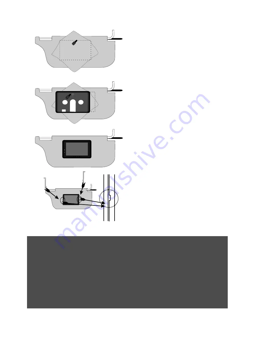
Route the cable through the visor

Run the supplied cable through the opening
and out to  the bottom of the visor. If possible,
conceal the wires using a shaft covering. 
Connect the power, ground and video leads to
test the MONITOR. Before connecting the 
monitor, pull the  connecting cable assembly
through the visor housing as shown in diagram.
Place sun-visor shroud into the opening and 
secure it with correct fasteners.

Install the sun-visor shroud

Pull the connecting cable through the center of 
the housing as shown in diagram, and secure
the sun-visor shroud  with correct fasteners

THIS SIDE UP

THIS SIDE UP

Insert the monitor

Push to insert the monitor 
to the sun-visor shroud.

THIS SIDE UP

THIS SIDE UP

Removal

Insert the release key between the monitor and 
visor shroud gap and pull it out to remove the 
monitor from headrest shroud.

10

Summary of Contents for PLVHR72

Page 1: ...INSTRUCTION MANUAL AURM 10B PLVHR72 7 Wide LCD Monitor With 4 Mounting Options www pyleaudio com PLHR71 ...

Page 2: ...Precautions Control Layout for monitor wireless remote Accessories Connection diagram Replacing the remote control battery Installing headrest with shroud Installing sun visor with shroud installing of headrest case Function setting Specifications 1 2 3 3 4 5 6 6 7 8 9 10 11 12 22 23 ...

Page 3: ... within the product s encloseure that may be of sufficient magnitude to constitute a risk of electric shock to persons This symbol is intended to alert the user to the presence of important operating and maintenance servicing instructions in the literature accompanying the appliance CAUTION RISK OF ELECTRIC SHOCK DO NOT OPEN Caution To reduce th risk of electric shock Do not remove cover or Back N...

Page 4: ...sk of electronic shock do not permit any of this equipment to become damp or wet from water or liquid If this does occur immediately unplug the power cord and send the monitor to your local dealer or service center as soon as possible 5 Do not attempt to repair open or disassemble any of the components Dangerous high voltages are present which may result in electric shock 6 Use only a power source...

Page 5: ...select menu function and decrease the selected parameters such as contrast color brightness etc Volume Increase Adjust increase headphone output volume Mute Press to Mute the sound press again to restore the previous volume level Control and layout for the remote control Adjust Decrease This multipurpose button serves to decrease the selected parameters such as volume contrast etc Menu Press to di...

Page 6: ...on Min Din Cable Remote Control Key for removing the monitor from headrest or visor shroud AURM 10B 5 Instruction Manual Accessories INSTRUCTION MANUAL AURM 10B PLVHR72 7 Wide LCD Monitor With 3 Mounting Options www pyleaudio com PLHR71 Headrest Case ...

Page 7: ...pecially on the dashboard 9 Keep the lithium battery out of the reach of children Should the battery be swallowed immediately consult a doctor 10 If the MONITOR does not operate even when you operate the remote control from a close range it is time to replace the battery use CR 2025 lithium battery refer ring to the label on the back of the basic control 11 Do not hold the battery with metallic tw...

Page 8: ...ns that would hinder the installation Use paper template to mark the area to be cut Cut the headrest Use an adjustable depth blade start your cut 1 4 inch inside one corner and cut diagonally across stopping 1 4 inch in from the other corner Repeat this procedure for the other two corners Remove foam obstructions Carefully peel off the material Set the adjustable blade to one inch depth and cut ar...

Page 9: ...hrough the headrest shroud as shown in diagram Place the headrest housing into the opening and secure with correct fasteners Install the headrest shroud Pull the connecting cable through the center of the shroud as shown in diagram and secure the headrest shroud with correct fasteners Removal Insert the release key between the monitor and headrest shroud gap and pull it out to remove the monitor f...

Page 10: ... Repeat this procedure for the other two corners Remove foam obstructions Carefully peel off the material Set the adjustable blade to one inch depth and cut around the edges of the hole staying 1 4 inch inside the edge Pull up one corner of the foam and use the blade to cut underneath Remove small section at a time ensure to be the uniform depth Use a dremel or other appropriate tools to remove ot...

Page 11: ...the wires using a shaft covering Connect the power ground and video leads to test the MONITOR Before connecting the monitor pull the connecting cable assembly through the visor housing as shown in diagram Place sun visor shroud into the opening and secure it with correct fasteners Install the sun visor shroud Pull the connecting cable through the center of the housing as shown in diagram and secur...

Page 12: ...11 Rear side of headrest Front side of headrest ...

Page 13: ...o choose the picture parameters setting Press MENU 1 to enter SEL MU SET EXIT RET OSD AV1 AV2 Return Video Signal Picture Parameters DDP OSD Setup Others Contrast Brightness Hue Saturation Gamma Function Scaling Return SEL MU ENT EXIT EXIT OSD Video Signal Picture Parameters DDP OSD Setup Others AV1 AV2 Return SEL MU ENT EXIT EXIT OSD Video Signal Picture Parameters DDP OSD Setup Others 2 1 3 Remo...

Page 14: ... 100 Preset 50 Video Signal Picture Parameters DDP OSD Setup Others Video Signal Picture Parameters DDP OSD Setup Others Video Signal Picture Parameters DDP OSD Setup Others Press the button 2or3 to adjust the symbol to choose contrast Press menu button 1 to enter contrast setting Contrast Narrows or widens the gap between black white darken brighten Press the button 2or3 to adjust the symbol to c...

Page 15: ...ess button 2 adjust brightness to lighter level Press button 3 adjust brightness to darken level Press button 1 to confirm setting Brightness adjustable level 0 100 Preset 50 Press the button 2or3 to adjust the symbol to choose hue Press menu button 1 to enter hue setting Hue adjusts reddish or green picture Press button 2 increases greenish level Press button 3 increases reddish level Press butto...

Page 16: ...ent selection An image with an aspect ratio of 4 3 regular picture Press the button 2or3 to adjust the symbol to choose paranromal Press menu button 1 setup as paranormal The symbol show current selection An image with an aspect ratio of 4 3 with only the left and right sides of the image being enlarged to fill the screen 2 1 3 Remote Monitor 2 1 3 Remote Monitor Enable Disable Return SEL MU ADJ E...

Page 17: ...eters DDP OSD Setup Others Press the button 2or3 to adjust the symbol to choose saturation Press menu button 1 to enter saturation setting Makes color appear lighter or darker Press button 2 makes colors appear darker Press button 3 makes colors appear lighter Press button 1 to confirm setting Saturation adjustable level 0 100 Preset 50 Press the button 2or3 to adjust the symbol to choose gamma Pr...

Page 18: ...3 to adjust the symbol to desired setting scaling Press menu button 1 to enter scaling setting Scaling adjusts picture size full screen letter box paranormal 2 1 3 Remote Monitor 2 1 3 Remote Monitor OSD Scaling Full Screen Letter Box Paranoma Return SEL MU SET EXIT RET Video Signal Picture Parameters DDP OSD Setup Others Press the button 2or3 to adjust the symbol to choose full screen Press menu ...

Page 19: ... to RETURN and press menu button 1 to exit Set enable as smartnous technology support Press the button 2or3 to adjust the symbol to choose disable Press menu button 1 setup as clearness picture The symbol show current selection Move the symbol to RETURN and press menu button 1 to exit Set disable as normal picture 2 1 3 Remote Monitor 2 1 3 Remote Monitor Language Select OSD Timeout Transparency I...

Page 20: ...r language setting Setting On Screen Display language Press the button 2or3 to adjust the symbol to desired language English Press menu button 1 setup language as English The symbol show current selection Move the symbol to RETURN and press menu button 1 to exit Set disable as normal picture 2 1 3 Remote Monitor 2 1 3 Remote Monitor Language Select OSD Timeout Transparency Information Memory Recal...

Page 21: ...60 Preset 30 seconds Press the button 2or3 to adjust the symbol to choose transparency setting Press menu button 1 to enter OSD transparency setting Transparency makes solid or transparency OSD display 2 1 3 Remote Monitor 2 1 3 Remote Monitor Transparency MU EXIT SAVE EXIT 0 OSD OSD Video Signal Picture Parameters DDP OSD Setup Others Press button 2 set increase transparency Press button 3 set re...

Page 22: ... to adjust the symbol to choose information Press menu button 1 to enter information Appear video input information Show video signal input information Move the symbol to RETURN and press menu button 1 to exit Set disable as normal picture 2 1 3 Remote Monitor 2 1 3 Remote Monitor Language Select OSD Timeout Transparency Information Memory Recall Return SEL MU ADJ EXIT RET OSD OSD Video Signal Pic...

Page 23: ...100 Preset 50 50 Adjust to the picture rotate OSD Video Signal Picture Parameters DDP OSD Setup Others Exit VCOM Adjust Display Model Rotate 2 1 3 Remote Monitor SEL MU ADJ EXIT RET OSD OSD Video Signal Picture Parameters DDP OSD Setup Others Exit VCOM Adjust Display Model Rotate Move the symbol to RETURN and press menu button 1 to exit Fully exit the setting 2 1 3 Remote Monitor SEL MU ADJ EXIT R...

Page 24: ...60 Response Time 15ms Backlight High Brightness CCFT 2 3 Luminance 350 cd m 1 Backlight Life 10 000 Hrs Contrast Ratio 300 1 o o Viewing Angle H V 120 100 o o o o Operation Temperature 20 C 70 C 2 F 158 F Video Color System Input NTSC PAL Compatible On Screen Display English Rear Video Input Terminals RCA x 1 1 Vp p 75 ohm Front Video Input Terminals 3 5mm Jack x1 1 Vp p 75 ohm Front Audio Input T...

Reviews: