background image

Notes:

• The unit can be installed on the vehicle

or the ships.

• Choose the mounting location where

the unit will not interfere with the normal
driving function of the driver.

• Before finally installing the unit, connect

the wiring temporarily and make sure
it is all connected up properly and the
unit and the system work properly.

• Use only the parts included with the

unit to ensure proper installation. The
use of unauthorized parts can cause
malfunctions.

• Consult with your nearest dealer if

installation requires the drilling of holes
or other modifications of the vehicle or
the ship.

• Install the unit where it does not get in

the driver’s way and cannot injure the
passenger if there is a sudden stop,
like an emergency stop.

• If installation angel exceeds 30˚ from

horizontal, the unit might not give its
optimum performance.

• Avoid installing the unit where it would

be subject to high temperature, such
as from direct sunlight, or from hot air,
from the heater, or where it would be
subject to dust, dirt or excessive
vibration.

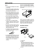
TAKE OUT SCREW BEFORE INSTALL

Before install the unit, please remove the
two screws.

NOTE: If this unit is installed on the ship,
you should use two pieces of plastic film
(30mmX20mm) supplied with the unit to
seal the two holes after remove the
screws. And this will be waterproof.

DIN FRONT-MOUNT

Installing the unit

1. Dashboard
2. Holder

After inserting the holder into the
dashboard, select the appropriate tab
according to the thickness of the
dashboard material and bend them
inwards to secure the holder in place.

3. Screw

3

INSTALLATION

(Fig. 1)

1

3

2

182

53

Take out screw before installation

30˚

Summary of Contents for PLCD16MRWB

Page 1: ...HER BAND AUDIO SYSTEM PLL Synthesizer Stereo Radio Digital Compact Disc Player Automatically Memory Storing Slide Down Detachable Panel Program CD Tracks CD Changer Control Auxiliary Input Function PL...

Page 2: ...Mount 3 Installing the unit 3 Removing the unit 4 Using the Detachable Front Panel 5 Wiring Connection 6 Operation 7 General Operation 11 Radio Operation 13 CD Operation 14 CD Changer Operation 15 Sp...

Page 3: ...n emergency stop If installation angel exceeds 30 from horizontal the unit might not give its optimum performance Avoid installing the unit where it would be subject to high temperature such as from d...

Page 4: ...of the unit in place The strap can be bent by hand to the desired angle 7 Plain washer Removing the unit 1 Before removing the unit press the OPEN button to slide down the front panel 2 Lever Insert t...

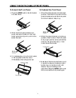
Page 5: ...after being removed To Reinstall the Front Panel 1 When the panel bracket is in slide down position insert the front panel into the panel bracket and push the front panel from the middle to slide it u...

Page 6: ...RONT Lch SPEAKER REAR Lch SPEAKER FRONT Rch SPEAKER REAR Rch SPEAKER Rch RED Lch WHITE GREY RCA CABLE ANTENNA SOCKET RED YELLOW BLACK BLUE POWER ANTENNA GROUND B MEMORY BACK UP IGNITION SWITCH B CD CH...

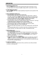
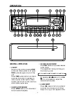
Page 7: ...rn on off the head unit Press button 1 for more than 3 seconds the button is operated to initial volume control button When system power turns on the volume is set to initial volume level 2 MUTE butto...

Page 8: ...Press buttons 6 to activate the cassette fast forward or rewind SELECT TRACKS FOR CD OR CDC OPERATION Press the buttons 6 shortly to move to the following track or the previous track Press the buttons...

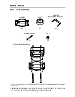
Page 9: ...se to the holder 2 Select the proper object then place the remote mounting bracket on the base and let the object go through the base and the mounting bracket 9 INSTALLATION INSTALLATION HARDWARE HOLD...

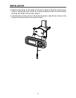
Page 10: ...screw holes on the bracket then use the two screws 4X50 and nuts to fix the bracket the base and holder to the proper location 4 Last install the remote control to the holder See below align the four...

Page 11: ...erated to initial volume control button When system power turns on the volume is set to initial volume level FACEPLATE RELEASE Press OPEN button 7 to slide down the removable faceplate SOUND ADJUSTMEN...

Page 12: ...ile in Clock Priority will temporarily display selected station frequency in RADIO mode or track number in CD CDC mode or state information in AUX IN mode Frequency Priority Press and hold DISP button...

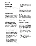
Page 13: ...SE button 2 shortly to scan preset station The radio is holding at that preset number for several seconds and then searches again Press AS PS ELAPSE button 2 again to stop scanning when desired statio...

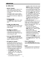
Page 14: ...r Program mode then PGM stars flashing and P 01 icon appear on the display 2 Press button 16 or button 17 to choose track number For example select track 6 then press MEM button 20 to memorize it and...

Page 15: ...select previous disc or next disc If there isn t any operation for several seconds it will exit shift mode automatically Note A Notes on discs 1 Attempting to use non standard shape discs e g square...

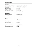
Page 16: ...um Output Power 4 x 50 Watts Current Drain 15 Ampere max CD PLAYER Signal to Noise Ratio More than 55 dB Channel Separation More than 50 dB Frequency Response 40 Hz 18 KHz RADIO FM Frequency Coverage...

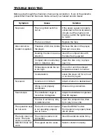
Page 17: ...rty or defective disc new one Temperature inside the car Cool off or until the ambient is too high temperature return to normal Condensation Leave the player off for an hour or so then try again No so...

Page 18: ......

Page 19: ......

Page 20: ...88 C1802 13...

Reviews: